A-4.2 Temperature Measuring Instruments
The heat that causes a change in temperature of a substance is called sensible heat. Heat energy is really a rate of molecular vibration; because these vibrations cannot be readily seen or evaluated, it might seem that temperatures would be difficult to determine. However, the fact that matter behaves in predictable ways when heated provides methods to measure temperature. For example, matter expands when heated, a property that can be used to indirectly determine the matter’s temperature.
Describe Temperature-Measuring Instruments
Any instrument used for measuring temperature is called a thermometer. Many sizes and types of thermometers have been developed. The choice of which type of thermometer to use depends on factors such as convenience, required accuracy, and range of temperature being measured. Almost all thermometers are calibrated in either degrees Celsius or Fahrenheit.
Both these degree systems are based on the freezing point (0°C and 32°F) and boiling point (100°C and 212°F) of water. The major difference in types of thermometers is not in calibration but in the method used to arrive at the reading.
Analogue Thermometers
The liquid-in-glass (glass-stem) thermometer consists of a small reservoir and a fine tube. The reservoir or bulb is filled with fluid, such as coloured alcohol or mercury (Figure 1). A change in temperature changes the volume of the liquid. Change in volume raises or lowers the level of the liquid in the tube. The temperature scale can be printed onto a mounted panel (left) or etched onto the glass tube (right). The longer the stem length, the smaller the graduations can be, and the more accurate the readings.
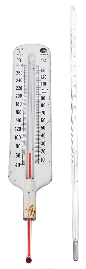

Glass-stem thermometers can be easily broken. Mercury is a very toxic or poisonous substance and must be handled and disposed of with great care if spilled.
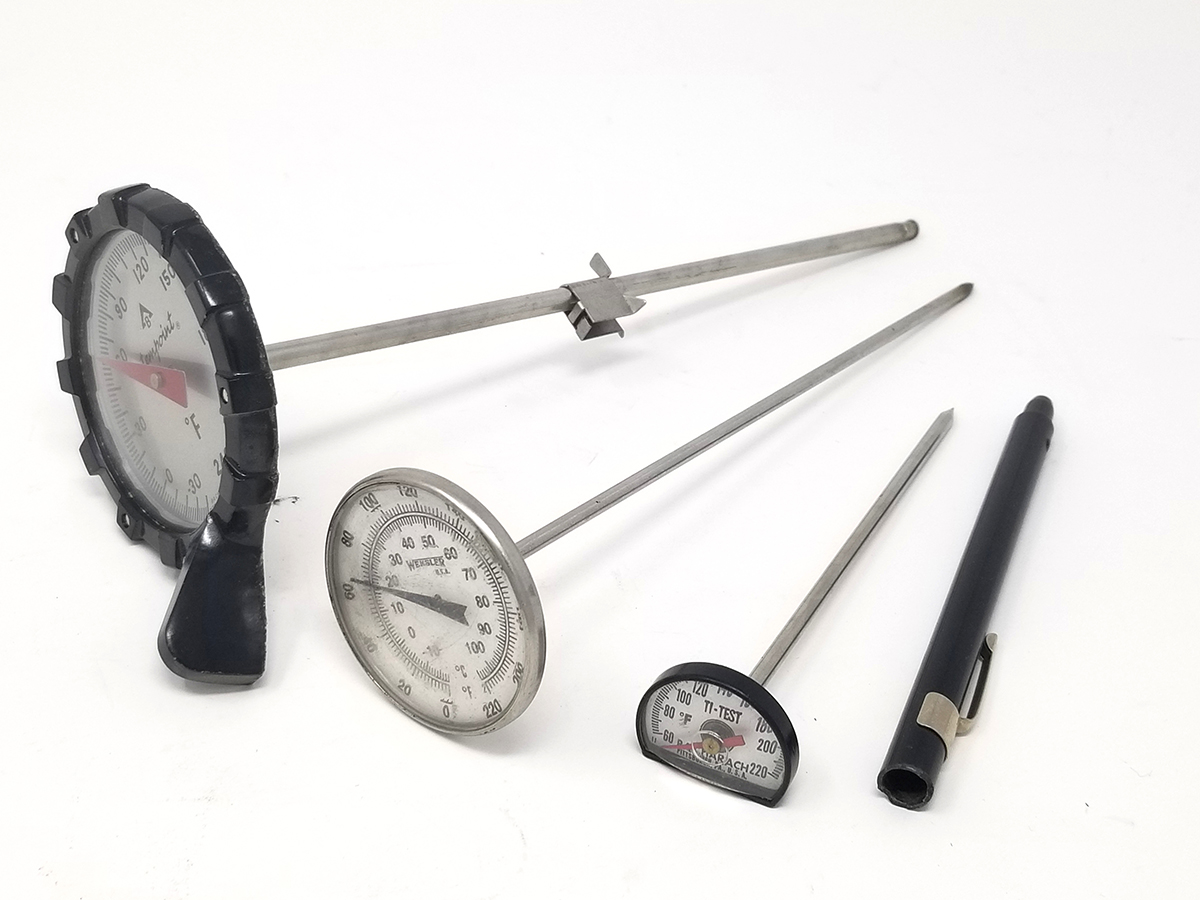
Dial thermometers are another common type of analogue thermometer. There are two general types: stem and flexible capillary.
Dial stem thermometers are made in a wide variety of dial sizes, stem lengths, and temperature ranges (Figure 2). They are more rugged and easily read than glass-stem thermometers. Their stems are small in diameter so that they can easily be inserted into small holes in ducts or through test port plugs. Dial stem thermometers usually use a bimetallic temperature-sensing element in the stem. Temperature changes cause a bend or twist of the element, and this movement is transmitted by a mechanical linkage to the pointer.
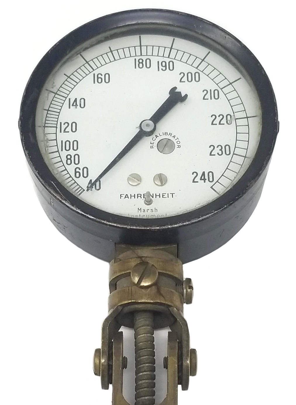
The other, less common type of dial thermometer is the flexible capillary type. It uses a large temperature-sensing bulb connected to the instrument with a capillary tube. The instrument contains a bourbon tube and operates the same way as a pressure gauge: as the temperature of the contained liquid or gas changes, the pressure exerted within the tube changes. These are also known as vapour tension thermometers and have the advantage of being able to read the temperature from a remote location. The capillary tube is usually covered with a braided metal protector. Capillary type dial graduations are non-linear (Figure 3). Notice that the distance between graduations increases as the temperature range increases. They are most accurate in the upper half of their range.
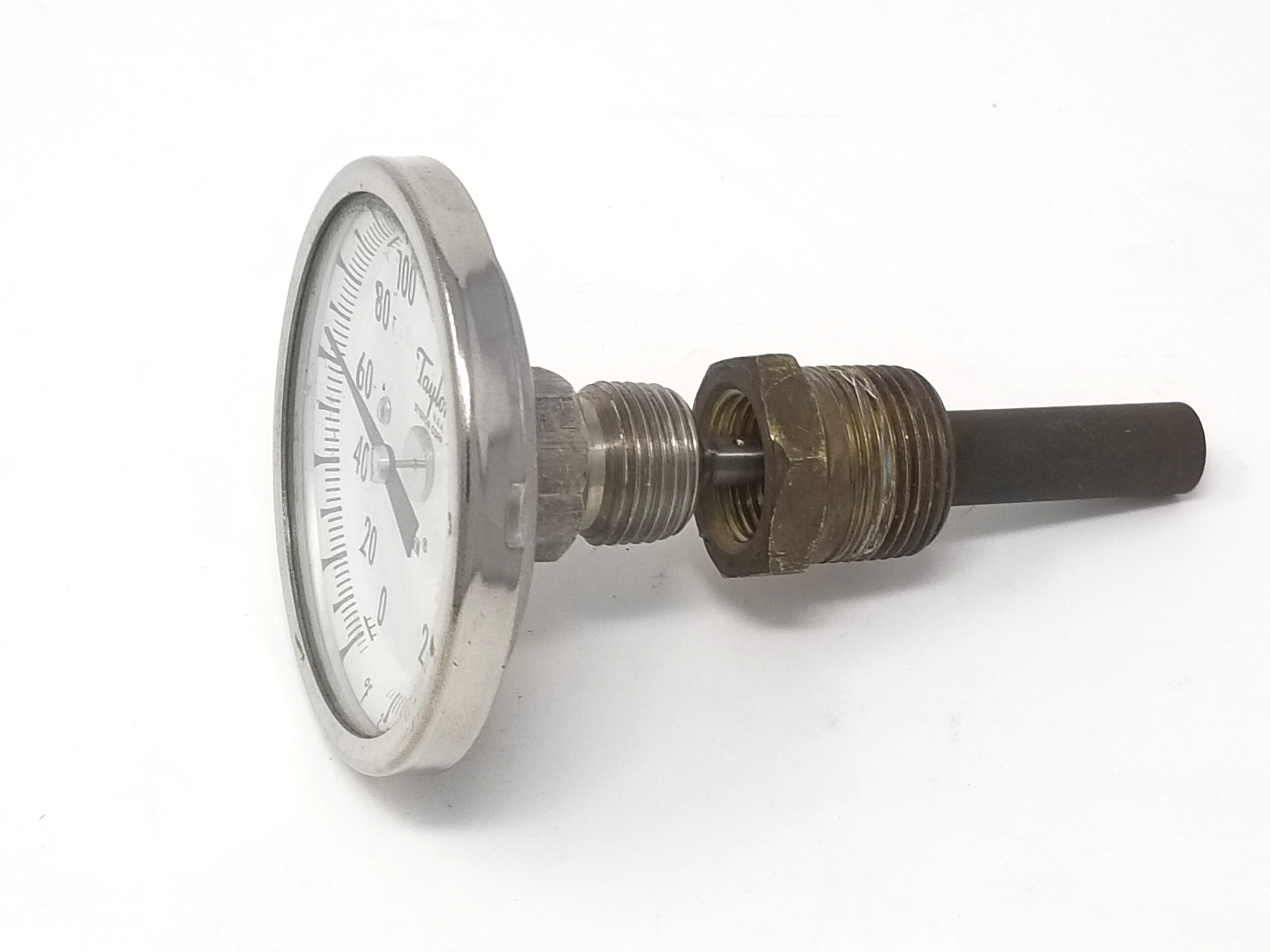
For permanently installed thermometers, the probe is often mounted in a cylindrical fitting called a thermowell (Figure 4), which is closed at one end and mounted in the process stream. The thermowell protects the sensor from the process fluid. If the sensor fails, it can easily be replaced without draining the vessel or piping. Thermodynamically, the process fluid transfers heat to the thermowell wall, which in turn transfers heat to the sensor. Since more mass is present with a sensor-well assembly than with a probe directly immersed into the process, the sensor’s response to process temperature changes is slowed by the addition of the well.
Digital Thermometers
Although analogue gauges are still used, digital thermometers are the most popular temperature-measuring instrument used today because they have better accuracy and a larger temperature range. For example, the simple folding digital pocket thermometer shown in Figure 5 has a temperature range of –50°C to 300°C, with an accuracy of ±1°C.
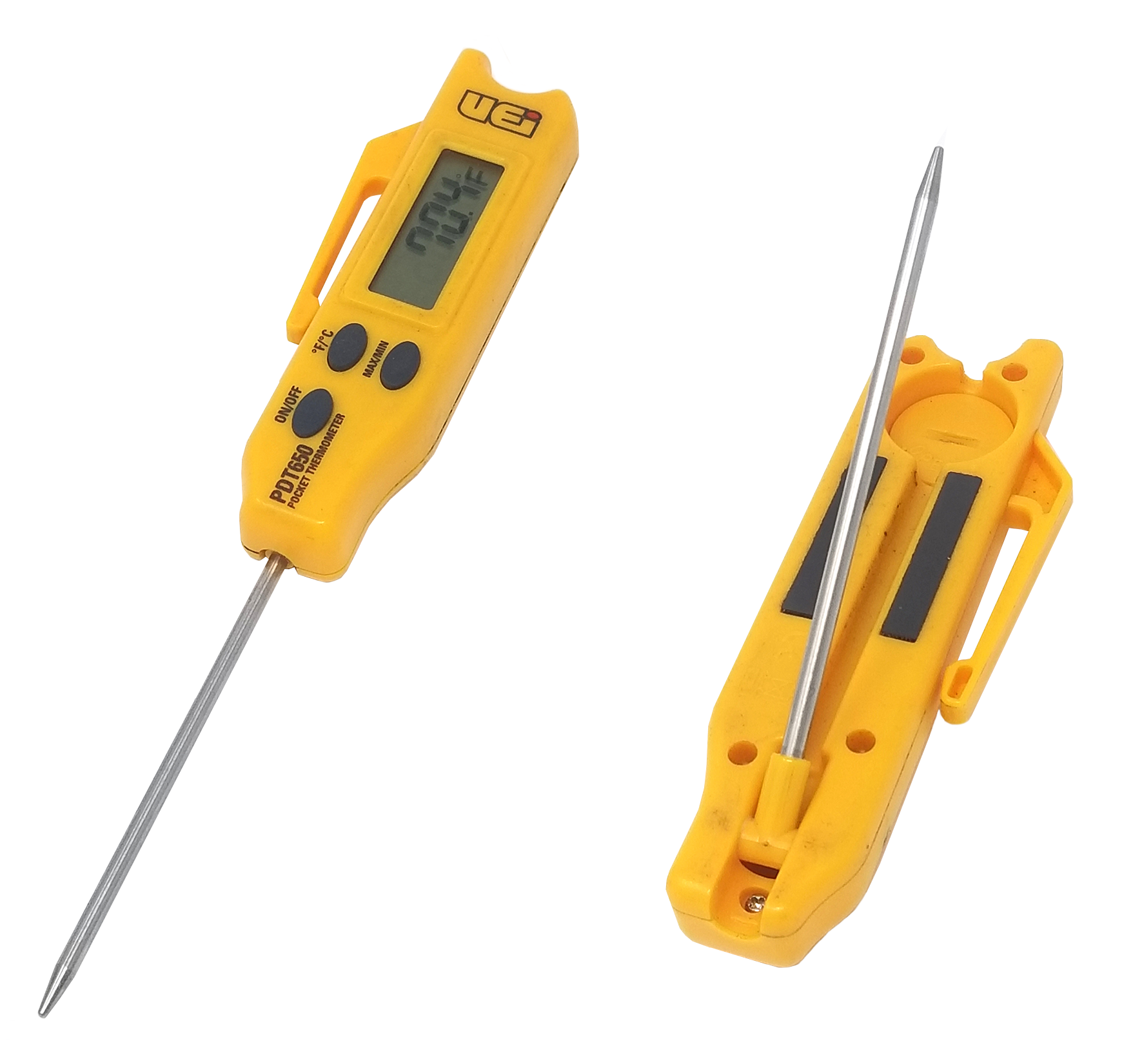
The only disadvantage of electronic/digital thermometers is the potential of a depleted battery. Digital thermometers have a sensor known as a temperature transducer. The transducer creates a voltage, current, or resistance change when there is a change of temperature. These are all analogue signals, which the thermometer takes and converts into a digital signal that it sends to the display drive.
There are three common types of sensors used by digital thermometers:
- Resistance temperature detectors (RTDs)
- Thermistors
- Thermocouples
All digital thermometers look similar, no matter which type of sensor the manufacturer uses. The following is a brief description of each of these sensors.
RTD
Electrical conductors change their electrical resistance as their temperature changes. Resistance drops as temperature drops and rises as temperature rises. The RTD wire is a pure material, typically platinum, which has a near linear resistance change with temperature. If the resistance of the platinum wire at a certain temperature is known (typically 100 Ω @ 0°C), this information is used to determine the temperature of the wire when the resistance changes. Therefore, an RTD thermometer is, in essence, an ohmmeter because it measures the resistance of the sensor and converts it into a temperature reading. RTDs can have a range of –200°C to +500°C.
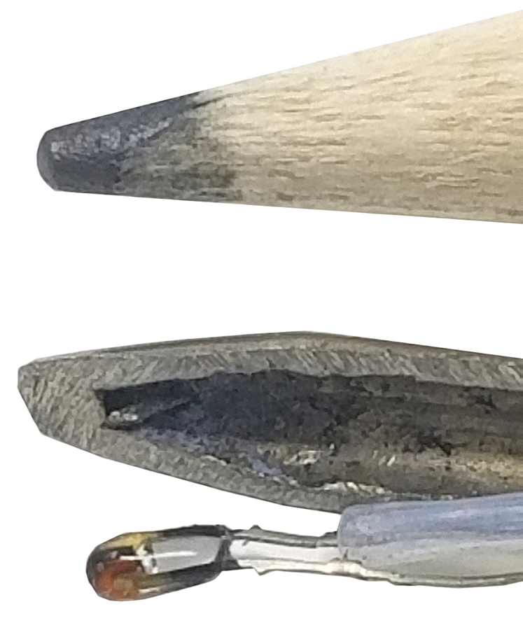
Many RTD elements consist of a length of fine wire wrapped around a ceramic or glass core, but other construction methods may be used. Because RTD elements are fragile, they are often housed in protective probes, as shown in Figure 6. The pencil is shown to give a size perspective.
Thermistor
The thermistor is a resistance sensor that changes its resistance in a non-linear way. Compared to RTDs, thermistors are more sensitive to small temperature changes and have a quicker response time because the resistance change is very large. However, thermistors have a smaller temperature range and stability. The typical operating temperature range of a thermistor is −55°C to +150°C.
Thermistors are of two opposite fundamental types:
- Negative temperature coefficient (NTC) thermistors: the resistance decreases as temperature rises. An NTC is commonly used as a temperature sensor.
- Positive temperature coefficient (PTC) thermistors: the resistance increases as temperature rises. PTC thermistors are commonly installed in series with a circuit and used to protect against overcurrent conditions, such as resettable fuses.
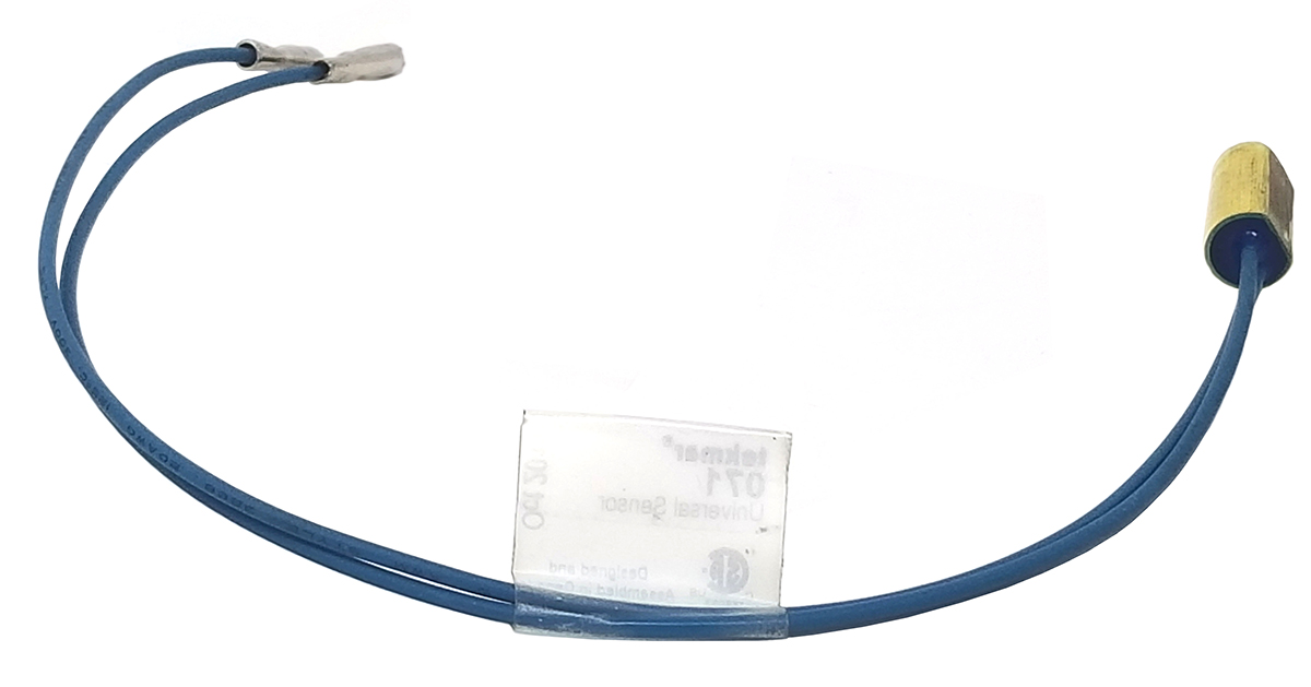
NTC thermistor elements come in many styles, such as glass-coated chips, epoxy-coated with bare or insulated lead wire, surface-mount, and rods and disks. Figure 7 shows a type of 10 kΩ (@ 25°C) NTC sensor commonly used in the HVAC industry. This thermistor’s resistance change would range from approximately 490 kΩ @ –46°C to approximately 0.55 kΩ @ 107°C.
Thermocouple
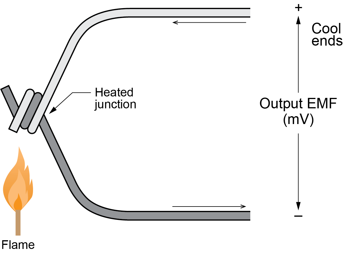
A thermocouple consists of two dissimilar electrical conductors joined at the hot junction. As temperature changes at the hot junction, a temperature proportional millivolt signal is read at the cold ends (Figure 8). This voltage can be interpreted to measure temperature.
There are different types of thermocouples, based on the different conductor types used. One of the most common types is the Type K, which is a coupling of Chromel and Alumel alloy wires. A Type K thermocouple has a wide temperature range from −270°C to 1,260°C and an output of 6.4 mV to 54.9 mV over this range. This wide range, combined with its ability to function in rugged environmental conditions and various atmospheres, makes it a commonly used temperature sensor. Type K thermocouples are less suitable for applications where smaller temperature differences need to be measured with an accuracy better than ±0.7°C.
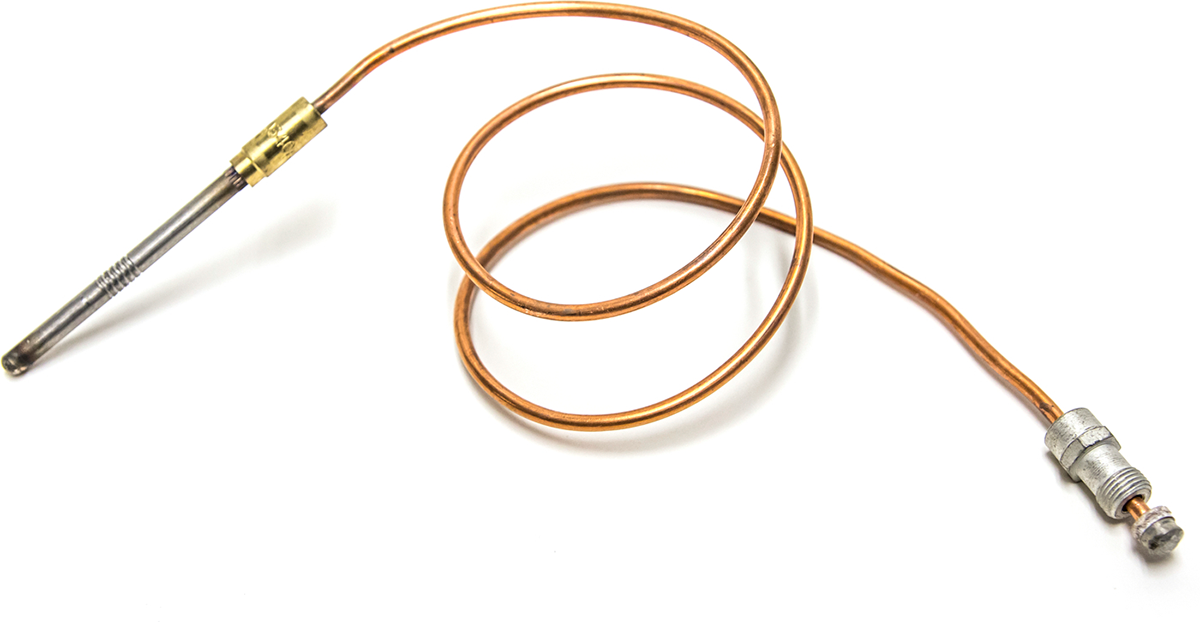
There are also different styles of thermocouples. Figure 9 is a grounded thermocouple, where the outer sheath and wire are welded together to form one junction at the probe tip. The outer copper sheath becomes part of the circuit. This thermocouple is used in a fail-safe circuit to sense when a gas pilot light is burning. The tip of the thermocouple is placed in the pilot flame, generating a voltage that operates the supply valve that feeds gas to the pilot.
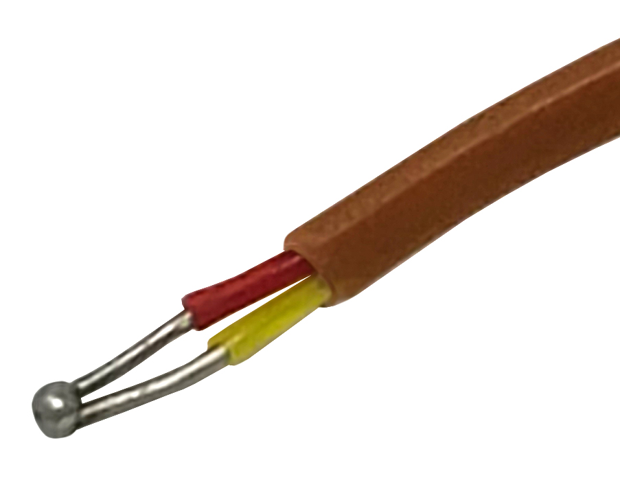
For exposed (bare wire) thermocouples, the wires are exposed where they are welded together, and this junction is inserted directly into the process (Figure 10).
All wires that make up the thermocouple must be insulated from each other, except at the sensing junction (hot junction). Any additional electrical contact between the wires or contact of a wire to other conductive objects can modify the voltage and give a false temperature reading.
Plastics are suitable insulators for low-temperature parts of a thermocouple, whereas other materials are be used for higher temperature applications. Because the entire wire makes up part of the thermocouple, the wire cannot be repaired or lengthened with ordinary conductors.
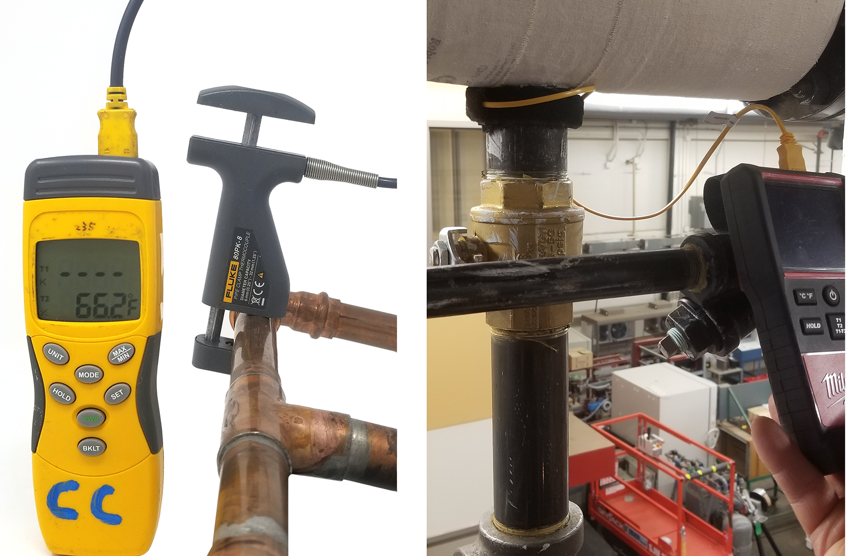
Type K thermocouples are commonly used on digital multimeters (DMM) (Figure 11), which have a temperature setting on the selector dial. The meter converts the output voltage level to temperature using a conversion formula.
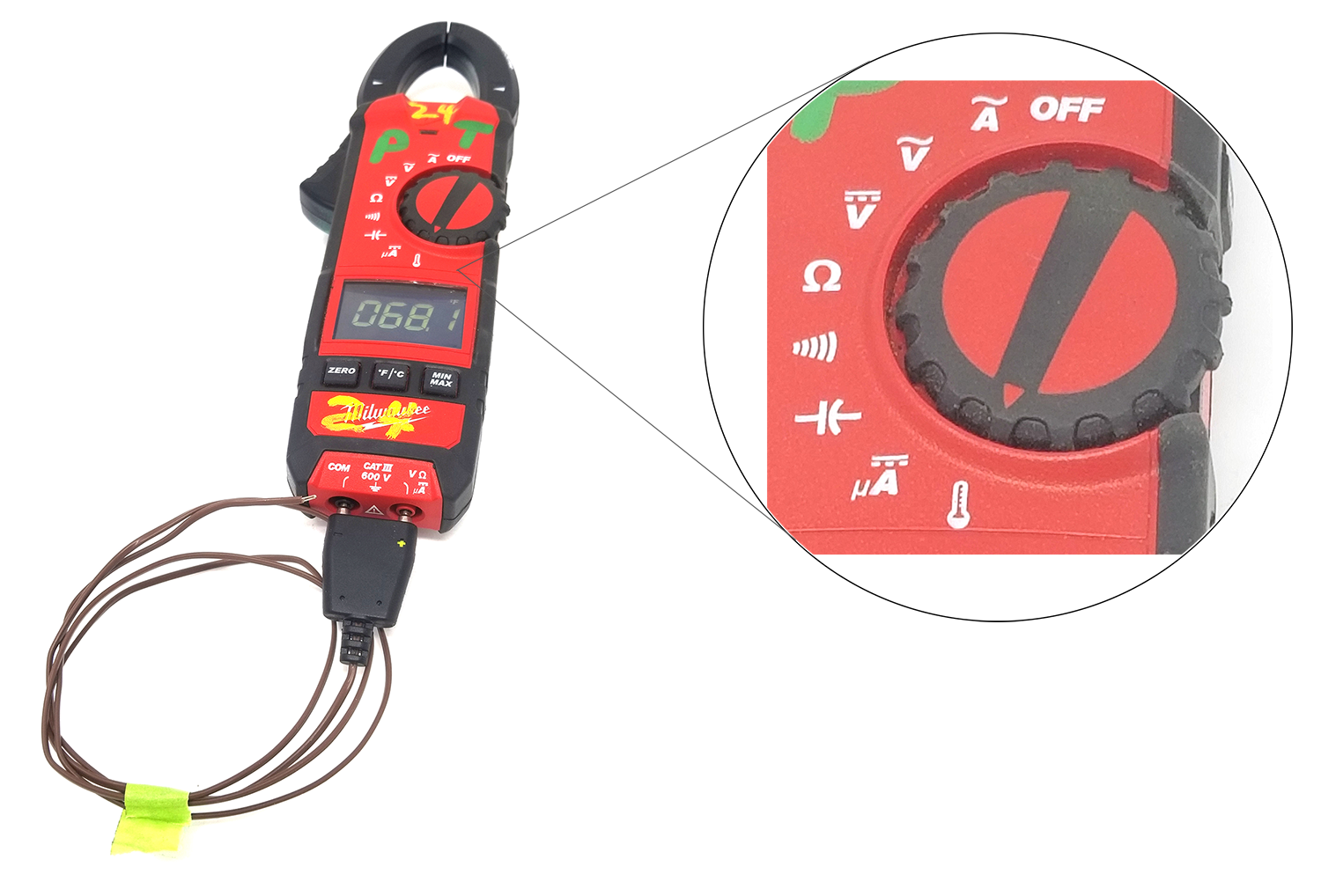
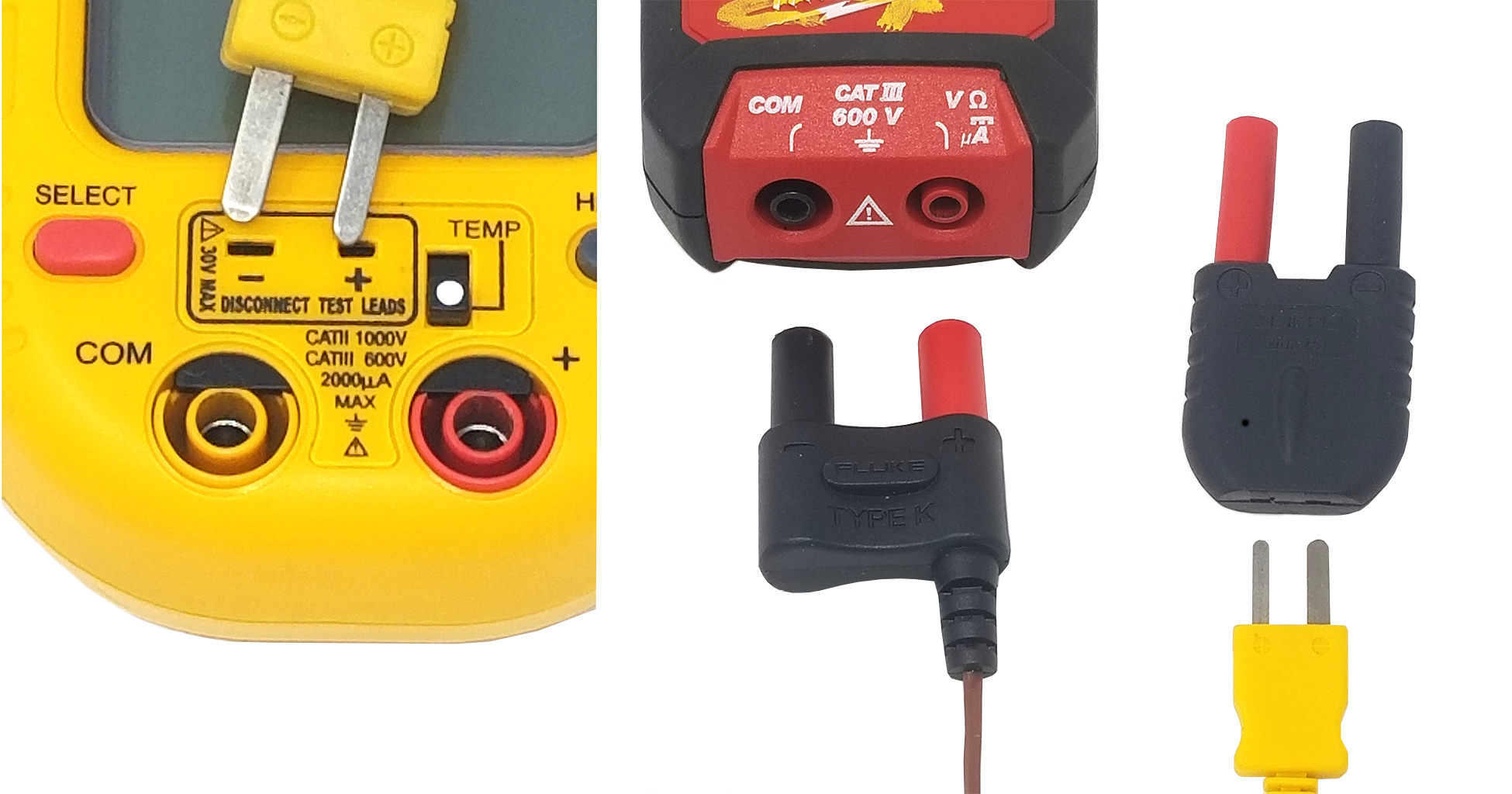
Figure 12 shows a couple of Type K thermocouples with different types of connectors. The type on the left is a very common universal flat-pin miniature thermocouple connector. Notice that when the switch is in the TEMP position, two partial black shutters block the electrical connection openings. Moving the switch out of the TEMP position opens the connection openings and thermocouple connections. The type in the middle image connects directly to the same terminals used for the electrical test leads. Alternatively, the adapter shown on the right can be used to connect the flat-pin style.
Pyrometer
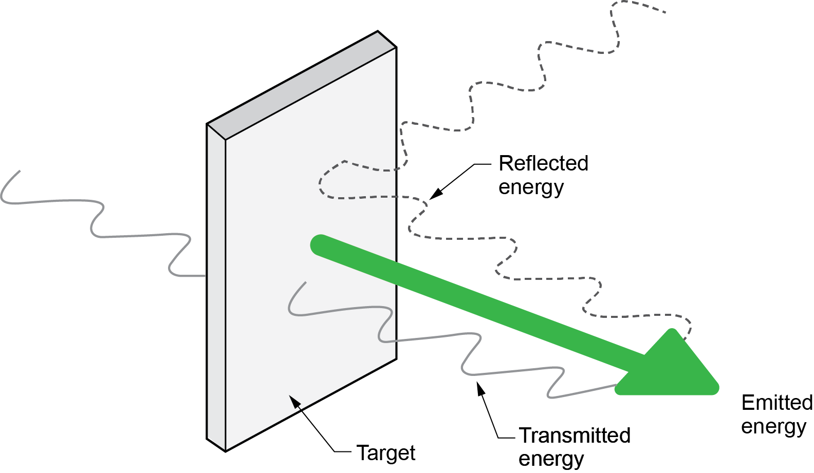
A pyrometer, by definition, refers to any remote-sensing thermometer. The modern pyrometer is a device that can determine the temperature of a surface from a distance, with no need for contact with the object. A pyrometer determines the temperature of a surface by the amount of thermal radiation it emits, which increases with temperature (Figure 13). The most common hand-held type is the infrared (IR) thermometer, which detects the invisible thermal infrared radiation the surface emits and translates the signal into a temperature reading.
IR thermometers are also called temperature guns, non-contact thermometers, or laser thermometers because they have a laser to help aim the thermometer (Figure 14).
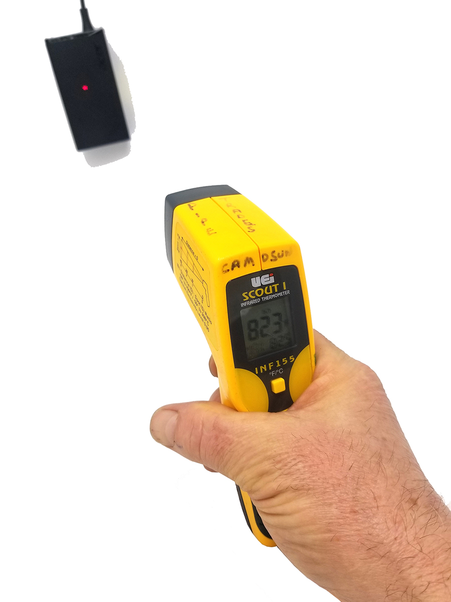
The IR thermometer has a relatively wide temperature range, from about −50°C to 400°C, with an accuracy of ±2°C. These optical pyrometers are especially suited for measuring moving objects or any surfaces that cannot be reached or touched.
Some types of infrared thermometers also include an input jack for connecting a Type K thermocouple probe to make contact temperature measurements. The probe can be used simultaneously while the thermometer is taking non-contact measurements, and both readings will be displayed.

Although the class of visible light lasers typically used are relatively safe, intentionally staring at the beam could lead to eye injury.
Use Temperature-Measuring Instruments
The operation of many mechanical systems that we use or install involves the flow or transfer of heat energy from one place to another. Whether it be the use of heating irons for poly fusion or the commissioning of space heating equipment, we need to observe temperatures to verify the proper transfer of heat energy.
Checking Accuracy
Always check the accuracy of a new thermometer or one that is unfamiliar. Portable dial thermometers can get out of calibration due to the presence of mechanical linkages and by being dropped. There are two basic methods for checking a thermometer’s accuracy.
The freezing point method is the simplest and most accurate:
- Fill a glass with crushed ice.
- Add clean water (distilled water is best) and stir.
- Wait for about three minutes.
- Insert the sensor of the thermometer into the ice filled water.
- Once the thermometer has adjusted, its reading should be holding steady at 0°C.
Another method is the boiling point method:
- Boil about six inches of water in a suitable container.
- When the water reaches its boiling point, place the sensor in the water, away from the sides and bottom of the container.
- Once the thermometer has adjusted its reading, it should be holding steady at 100 °C if you are below 300 metres in elevation. Higher elevations will have a lower boiling temperature.
Calibration
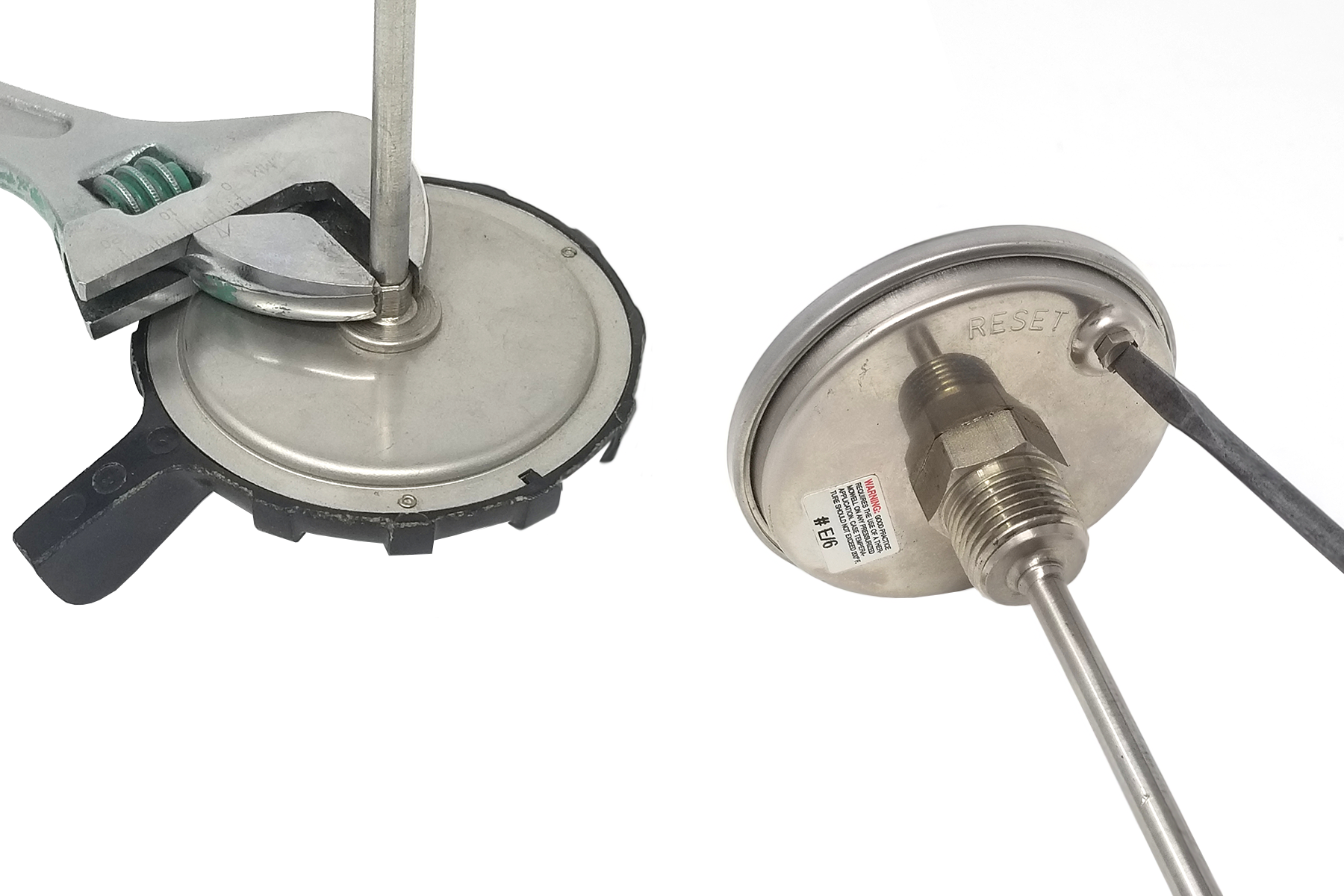
Some dial thermometers have a calibration nut on the back of the dial head. Hold the nut securely with a wrench and rotate the head until it reads correctly (Figure 15). Other styles may include a separate adjustment or reset screw for calibration, as shown on the right.
For digital thermometers, it is important to check the manufacturer’s instructions regarding calibration. Inexpensive digital pocket thermometers may not be able to be calibrated. Others may have a reset button that can be used when the freezing point test is performed.
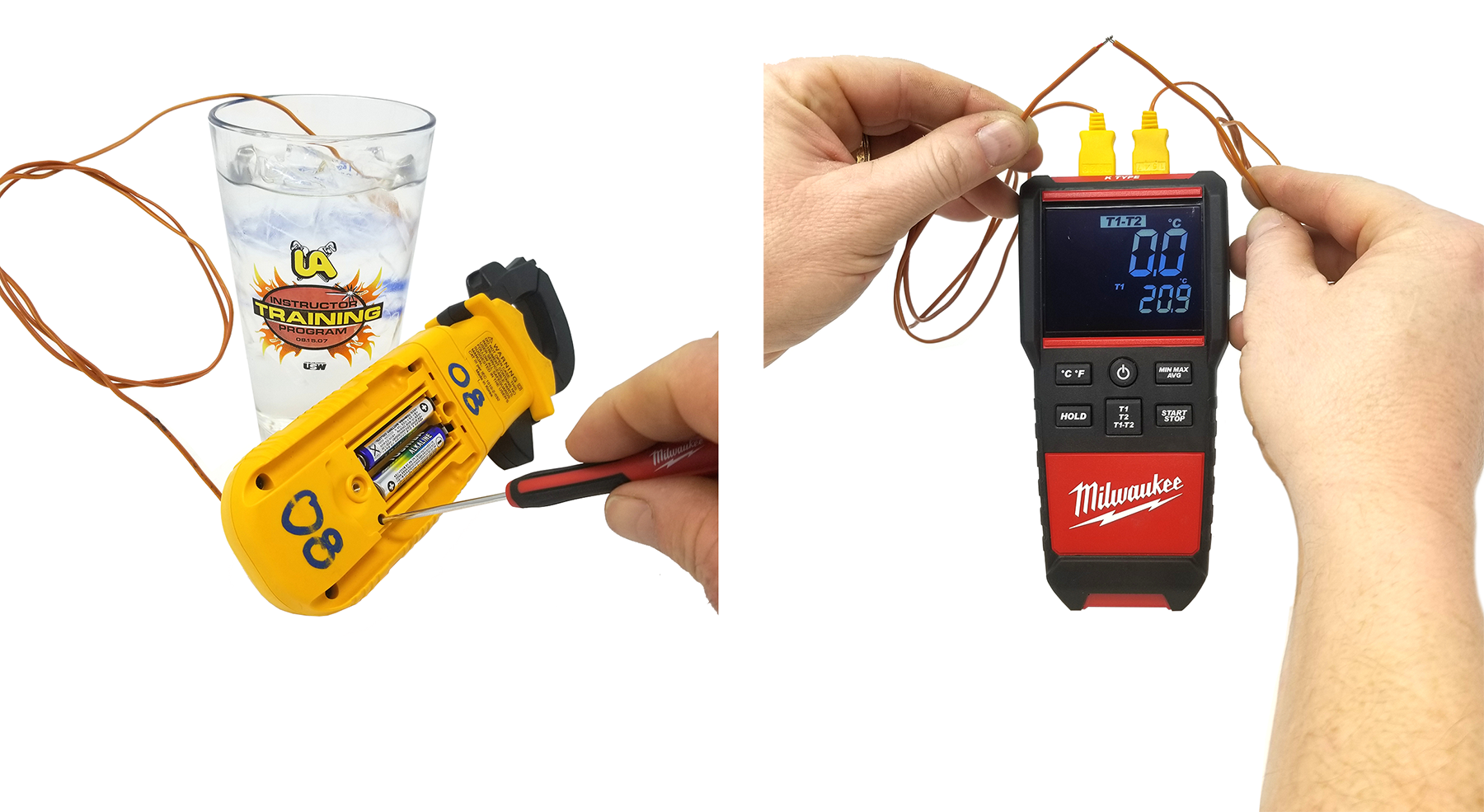
Digital contact temperature meters, which use plug-in thermocouples, may have an adjustable potentiometer for calibration. Use a fine-tip standard screwdriver to make adjustments through the access port (Figure 16, left). Other meters may require the instrument to be sent to the manufacturer’s service facility for calibration.
When using a meter designed to check temperature differential, perform a simple accuracy test by holding the two thermocouples together while on T1-T2 setting (Figure 16, right), which should result in a reading of zero once the probes stabilize.
Digital contact thermometers that do not give physical access to the calibration potentiometer may have a display “Offset” function. This function is one of the setup options, which allows the operator to adjust the display to compensate for the errors of a specific thermocouple.
Taking Measurements
Be sure to read the manufacturer’s operating instructions and pay particular attention to all safety warnings.
The probe of a contact thermometer may be damaged if the specified measurement range is exceeded. When using any type of contact thermometer, it is important that the end of the probe be in contact only with the product being measured. The sensor is located at the end of the probe, therefore, contact with the stem or wire does not affect the reading. Verify that the initial reading indicates the ambient air temperature before inserting the probe. Digital instruments have a number of display functions, such as Scale (°C/°F), HOLD, MAX/MIN, AVG, OFFSET, T1, T2, T1-T2, LOG, and time elapsed. Pay attention to the LCD display function descriptions to ensure correct interpretations of the readings. Digital meters typically have an auto off function that automatically powers down the thermometer after a period of inactivity.
For some temperature measurements, the bare-wire or needle-style probes can be difficult to use. For these measurements, many probe designs are available for special applications. As long as they are a matching thermocouple type (typically Type K), they will plug directly into any digital meter.
Figure 17 shows a couple of other thermocouples configured with clamps or straps, which free up the operator’s hands to make adjustments or record readings.
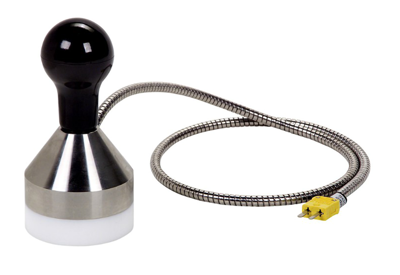
The probe shown in Figure 18 is designed for use on any flat surfaces. These types of probes are convenient for checking the temperature of heating irons, such as those used for poly fusion. The weighted probe also has a teflon coating to stop it from scratching surfaces that it comes into contact with.
IR Measurements
To take a measurement with an IR thermometer, point the thermometer at the object and pull the trigger. This will turn the unit on, and the object’s temperature will show on the display. As long as the trigger is depressed, the unit will continue to update the present reading and other functions, such as minimum or maximum temperatures, measured during that period. Once the trigger is released, it will hold its reading for a short period of time.
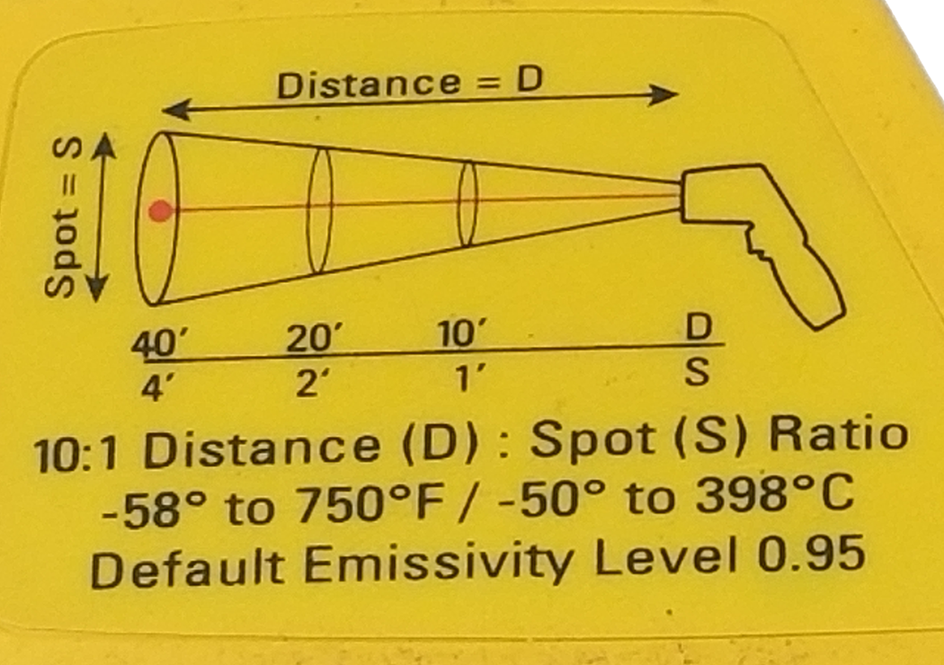
The laser pointer is used only to help aim the thermometer. It is not related to temperature measurement. As the distance (D) from the object being measured increases, the spot size (S) of the area measured by the unit becomes larger. This is called the distance-to-spot ratio (D:S) and must be considered when determining field of view.
Figure 19 shows a unit with a 10:1 D:S; therefore, measurements taken from a distance of 1 m (1,000 mm) would have a circular field of view with a diameter of 0.1 m (100 mm). For accurate measurements, make sure that the target is larger than the unit’s spot size. The smaller the target, the closer the thermometer should be.
The other factor that affects the accuracy of an infrared thermometer is emissivity. Emissivity compares the energy-emitting characteristics of materials to the energy emitted from a black-body source. Surfaces closest to the black-body level would be flat black, and those farthest from it would be mirror or chrome surfaces. Although most infrared thermometers have a fixed emissivity of 0.95, most items measured provide a reasonably accurate result. To compensate for inaccurate readings that may result from measuring shiny metal surfaces, the surface to be measured can be covered with electrical tape or flat black paint. Some instruments have a fully adjustable emissivity, which enables the instrument to be fine-tuned for a specific application.
Applications
Temperature measurements are necessary to verify the proper operation of any heating equipment and are commonly taken when working on any type of HVAC and hydronic equipment. Some common examples include:
- Checking temperature difference between supply and return air on a forced air furnace
- Checking return water temperatures on individual loops of a hydronic heating system to balance flow or troubleshoot
- Checking floor surface temperatures of a hydronic radiant system to verify that it is operating as designed
- Measuring flue-gas temperature of gas-fired appliances to check efficiency
- Measuring a faucet’s hot water temperature when adjusting a mixing valve or high-limit stop
 Self-Test A-4.2 Temperature Measuring Instruments
Complete Self-Test A-4.2 and check your answers.
If you are using a printed copy, please find Self-Test A-4.2 and Answer Key at the end of this section. If you prefer, you can scan the QR code with your digital device to go directly to the interactive Self-Test.

References
Cooper Atkins: Weighted griddle surface probe CA-50014-K. (n.d.). Cooper-Atkins™ | Copeland US. Image found on: https://safcoaustralia.com.au/product/weighted-griddle-surface-probe-ca-50014-k/
Fluke. (2010, August). Figure 5. How the thermometer works [adapted image]. In 56x infrared thermometers user manual [PDF]. https://dam-assets.fluke.com/s3fs-public/56x_____umeng0000.pdf
Skilled Trades BC. (2021). Book 1: Fuel gas systems, Heating and cooling systems. Plumber apprenticeship program level 2 book 1 Harmonized. Crown Publications: King’s Printer for British Columbia.
Trades Training BC. (2021). A-4: Use technical instruments and testers. In: Plumber Apprenticeship Program: Level 2. Industry Training Authority, BC.
Media Attributions
All figures are used with permission from Skilled Trades BC (2021) unless otherwise noted.
- Figures 1–7, 9–12, 14–17, and 19 are by Rod Lidstone and used under a CC BY licence.
- Figure 13 was originally adapted for Skilled Trades BC (2021) by Trades Training BC from Fluke (2010). It is used under the Fair Dealing guidelines for educational purposes.
- Figure 18 was originally adapted for Skilled Trades BC (2021) by Trades Training BC from Cooper Atkins™ (n.d.). It is used under the Fair Dealing guidelines for educational purposes.
The heat that causes a change in temperature of a substance and can be felt or measured by a thermometer; it is the heat exchanged by a body or system that changes its temperature without altering its phase, volume, or pressure; for instance, sensible heat warms water but does not melt ice or evaporate water. (Section A-4.2)
A thermometer that consists of a small reservoir and a fine tube; the reservoir, or bulb, is filled with a fluid like colored alcohol or mercury; when the temperature changes, the liquid's volume changes, causing the liquid level in the tube to rise or fall. (Section A-4.2)
A common type of analogue thermometer available in two general types: stem and flexible capillary. They typically use a bimetallic temperature-sensing element in the stem, where temperature changes cause the element to bend or twist, moving the pointer via a mechanical linkage. (Section A-4.2)
A device that features a large temperature-sensing bulb connected to the instrument via a capillary tube; it employs a Bourdon tube mechanism similar to a pressure gauge: as the temperature of the enclosed liquid or gas varies, so does the pressure within the tube; these devices, also referred to as vapor tension thermometers, offer the advantage of remote temperature reading capabilities. (Section A-4.2)
See flexible capillary dial thermometer. (Section A-4.2)
A cylindrical fitting designed to shield temperature sensors used for monitoring industrial processes; consists of a closed-end tube that is installed on the wall of piping or vessels where the fluid flows, safeguarding the temperature sensor inside. (Section A-4.2)
A device that transforms thermal energy into other physical forms such as mechanical energy, pressure, or electrical signals. For instance, a thermocouple generates an electrical potential difference based on temperature variations across its terminals. (Section A-4.2)
A device that measures temperature by detecting changes in electrical resistance; RTDs can have a range of –200°C to +500°C. (Section A-4.2)
A tool used to measure how much something resists the flow of electricity (electrical resistance); it tells you the resistance in units called ohms (Ω); multimeters can serve as ohmmeters when set to resistance-measuring mode; to measure resistance, an ohmmeter applies a current to the circuit or component under test. (Section A-4.2 and Section A-4.3)
A type of semiconductor resistor whose resistance varies significantly with temperature, unlike standard resistors (the term "thermistor" combines "thermal" and "resistor"); these serve as temperature sensors in diverse applications and are categorized into two types: NTC (negative temperature coefficient) and PTC (positive temperature coefficient). (Section A-4.2)
Resistors with a negative temperature coefficient, which means that their resistance decreases as the temperature increases; primarily used as resistive temperature sensors and current-limiting devices; unlike RTDs, which are made from metals, NTC thermistors are generally made of ceramics or polymers; their temperature sensitivity ranges from approximately -3% to -6% per degree Celsius. (Section A-4.2)
Resistors with a positive temperature coefficient, which means that the resistance increases with increasing temperature; they are made from materials such as silicon or barium titanate, known for their high resistance properties, and they have various uses such as temperature sensors, self-regulating heaters, and resettable fuses. (Section A-4.2)
Also referred to as a "thermoelectrical thermometer," an electrical device composed of two different electrical conductors that form an electrical junction; through the Seebeck effect, generates a voltage that varies with temperature, allowing for temperature measurement; extensively used as temperature sensors. (Section A-4.2)
A thermocouple with Chromel and Alumel alloy wires, offering a broad temperature range from −270°C to 1,260°C; it generates an output of 6.4 to 54.9 mV across this range and excels in rugged environments and diverse atmospheres; Due to its versatility, widely employed as a temperature sensor, though it may not provide optimal accuracy for measuring smaller temperature differentials better than ±0.7°C. (Section A-4.2)
An electronic tool that combines the features of a voltmeter, an ammeter, and an ohmmeter; it measures electricity, voltage, and resistance and shows these measurements on a digital screen using numbers, making it easy to read and understand. (Section A-4.2 and Section A-4.3)
A type of remote-sensing thermometer that measures the temperature of a surface without making direct contact; it determines temperature by detecting the thermal radiation emitted by the surface, which rises as the temperature increases. (Section A-4.2)
An Instrument that measures temperature by detecting thermal radiation emitted by the object being measured, often referred to as black-body radiation; also known as a laser thermometer due to use of a laser for aiming, or as a non-contact thermometer or temperature gun because it can measure temperature from a distance; by assessing the amount of infrared energy emitted and considering emissivity, infrared thermometers can estimate the object's temperature within a specified range; belongs to the category of devices known as "thermal radiation thermometers." (Section A-4.2)
An instrument for measuring or adjusting small electrical potentials. (Section A-4.2)
A ratio that tells you how far you need to be from an object to measure its temperature accurately with a thermometer; a higher D:S ratio means you can measure temperature from farther away, like using a zoom on a camera to focus on something far off. (Section A-4.2)
A number from 0 to 1 that indicates how much heat a material lets out as radiation; 1 means it gives off radiation well, like a perfect black object; lower numbers mean less heat is released. This matters in infrared thermometers, where knowing emissivity helps get accurate temperature readings by adjusting for how materials reflect or emit heat. (Section A-4.2)
A "black-body source" is an object that is perfect at absorbing and giving off heat energy. It doesn't reflect any light; instead, it takes in all the energy that hits it and then emits the maximum amount of energy possible for its temperature. When we talk about "emissivity," we're comparing how much energy a real object emits compared to this perfect black body. So, if a material has high emissivity, it's very good at emitting heat energy, like the black body. If it has low emissivity, it's not as good at emitting heat. (Section A-4.2)
