A-3.4 The Building as a System
The purpose of a building is to provide comfort for its occupants. Technological advances in the construction industry that make buildings more energy-efficient, comfortable, and cost-effective have carried with them the need for tradespeople to understand the building as a whole system.
The building system is made up of four major subsystems:
- Occupants
- Building envelope
- Outside environment
- Mechanical and electrical equipment
These subsystems all affect the flow of air, heat, and moisture to and from the building. Although these flow factors are often interrelated, this section will focus on air flow.
Types of Buildings
There are many different ways of categorizing building types, including:
- The purpose they are used for, such as residential, educational, institutional, business, storage/warehouse, industrial, and so on
- Design and height, such as multi-storey or high rise, detached, or semidetached
- Whether or not the building was designed and built using strategies aimed at improving performance in areas of energy efficiency and environmental responsibility
For the purpose of HVAC systems, the tightness of the building is often used to categorize the building because it has the greatest effect on the flow factors. With the introduction of new building materials and techniques and the growing emphasis on energy efficiency, modern buildings have become increasingly airtight.
Having a sound knowledge of “building as a system” principles helps to minimize conditions that can affect appliance performance and ensures the health and safety of the occupants. For example, combustion appliances that operated quite well in the relatively leaky buildings of the past may not operate safely in air-sealed modern buildings or retrofitted homes.
Building Envelope
The building envelope is the physical separator between the conditioned and unconditioned environment.
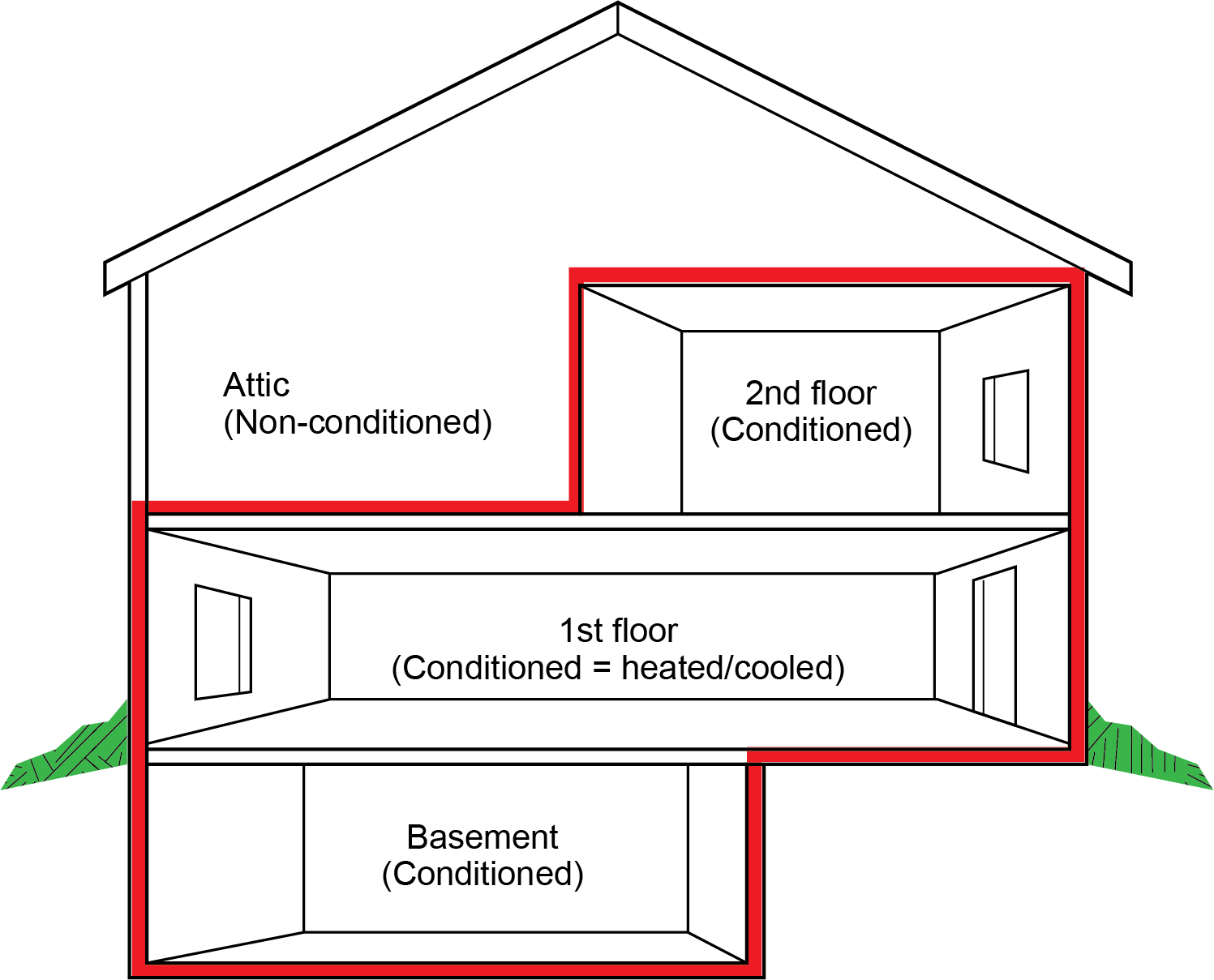
While the building envelope is a silhouette of sorts, each part of the building envelope must be thought of as a collection of smaller pieces working together to provide structural support.
Building envelope components work together to perform two basic but critical functions: provide structural support and control the flow factors. The function of controlling the flow of moisture, heat, and air is at the core of good building performance.
The control of air flow, including flow through the enclosure, is important to ensure indoor air quality.
The physical components of the envelope include the foundation, roof, walls, doors, windows, ceiling, and related barriers and insulation. Building envelopes are often characterized as either “tight” or “loose.” A loose building envelope allows more of a natural air transfer to occur. These types of building envelopes make the building draftier, more uncomfortable, and harder to regulate temperature levels. A tight building envelope allows for a high level of control over indoor air quality, temperature, humidity levels, and energy consumption. Additionally, good building envelopes that prevent drafts and other air leaks allow for better control of the inside air pressure.
It is impossible and unsafe to completely seal a building; however, every effort should be made to limit air and moisture leak points and increase insulation. The region and location of the building will have different environmental conditions (e.g., weather and ground conditions) that will affect the selection of the available materials used to make up the layers of the building envelope.
Building Ventilation Air
Indoor air quality is directly related to levels of air pollution. Ventilation is the main method used to control indoor air quality by removing indoor contaminants and replenishing stale or over-moist air with fresh outside air. Inadequate ventilation can lead to mould, high concentrations of CO2, and other indoor air pollutants, which can lead to adverse health outcomes. Frequent air exchange ensures that pollutants from household air are removed with speed and efficiency. The BC Building Code (BCBC) requires the installation of a principle ventilation system to ensure that an adequate amount of ventilation air is provided.
There are a number of ventilation options found in the BCBC that are categorized as either mechanical ventilation, natural ventilation, or mixed-mode ventilation.
Soil Gas
Outdoor air entering a dwelling through above-grade leaks in the building envelope normally improves the indoor air quality in the dwelling by reducing the concentrations of pollutants and water vapour. On the other hand, air entering a dwelling through below-grade leaks in the envelope may increase the water vapour content of the indoor air and may also bring in a number of pollutants picked up from the soil. This mixture of air, water vapour, and pollutants is sometimes referred to as “soil gas.” Air contaminants of concern, such as radon, must be removed at their point of origin.
Radon Mitigation
Radon is a colourless, odourless radioactive gas that occurs naturally as a result of radium decaying. It is found to varying degrees as a component of soil gas in all regions of Canada and is known to enter dwelling units by infiltration into basements and crawlspaces. The presence of radon in sufficient quantity can lead to an increased risk of lung cancer.
The principal method of resisting the ingress of all soil gases is to seal the interface between the soil and the occupied space as much as is reasonably practicable. In addition, various sections of the BCBC require the application of certain radon exclusion measures in all dwellings. The completion of a subfloor depressurization system may be necessary to reduce the radon concentration to a level below the guideline specified by Health Canada.
The principal method of excluding radon is to install a subfloor depressurization system to ensure that the pressure difference across the ground/space interface is positive (i.e., toward the outside) so that the inward flow of radon through any remaining leaks will be minimized.
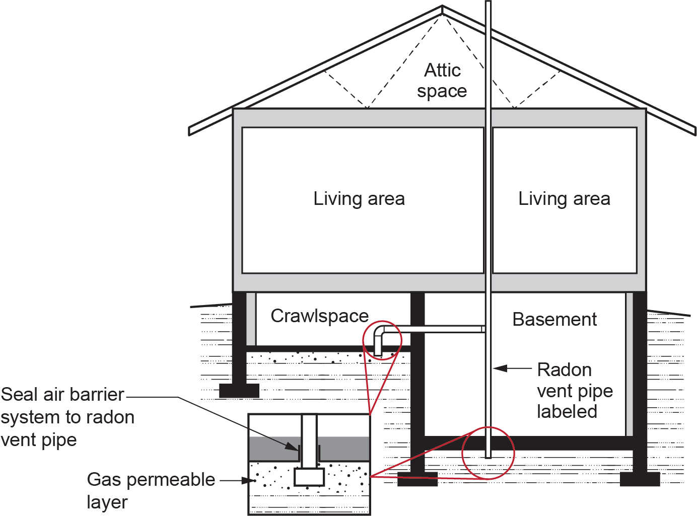
The most common and efficient soil depressurization systems require the following (see Figure 2):
- Space for the movement of soil gases between the ground and the air barrier system (see the gas permeable layer in Figure 2) into which a radon vent pipe is inserted.
- Extension of the radon vent pipe to the exterior of the building, terminating in a safe location.
- The radon vent pipe can be mechanically assisted, typically by means of a fan installed along the pipe, to create a negative pressure in the space between the air barrier system and the ground and to exhaust soil gases outside the building.
Building Make-Up Air
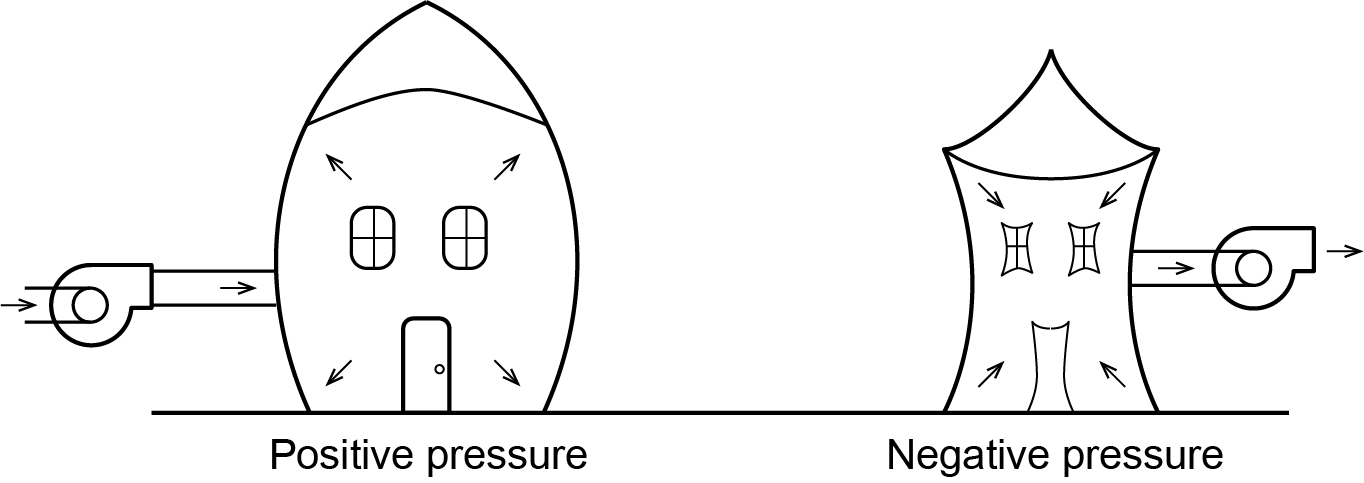
Proper air flow throughout a building depends upon balanced pressures. Excessive removal of air can create a negative pressure in the building that leads to inward pressure (Figure 3). Additionally, make-up air may be required to offset the air removed by appliances with large exhaust fans. The additional make-up air supply equipment must supply outdoor air at a rate that matches the exhaust appliance.
Oversupply of air to the building can drive the warm, moist indoor air into the walls, causing greater heat loss and moisture damage. If the building contains any natural draft gas appliances, the building depressurization must be limited to 5 Pa to eliminate the risk of backdrafting. A balanced flow of incoming and outgoing air is required for comfort and safety.
Ventilation Equipment
Every dwelling unit must include a principal ventilation system. There are many ways of ventilating residential dwellings, and the codes and standards play a large part in deciding what type is appropriate.
There are three basic concerns related to the mechanical ventilation of a building:
- Bringing in the proper amount of ventilation air
- Distributing the air to the required locations
- Avoiding excessive pressurization or depressurization
Previous editions of the British Columbia Building Code relied on ventilation through the building envelope in combination with an exhaust or supply fan. However, with the increased attention on the continuity of the building’s air barrier system, relying on the exfiltration or infiltration through the building envelop creates an unbalanced house. Combined mechanical ventilation systems are superior because they use both supply and exhaust fans in tandem to create a balanced system.
Air Supply Equipment
The ventilation air supply is often drawn through a controlled outdoor inlet connected to the return air ducting of the forced air recirculating system.
For buildings whose make-up air requirements require large-scale exhaust equipment, a separate supply fan must be interconnected with the exhaust fan. The outdoor air is tempered to at least 1°C before being introduced to a normally unoccupied area of the dwelling unit or house or to at least 12°C before being introduced to occupied areas.
Outside air intakes must be located away from sources of contaminants, such as vehicle exhaust or chemical vapours, and shielded from weather.
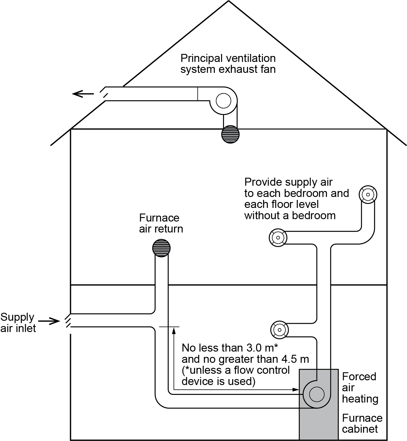
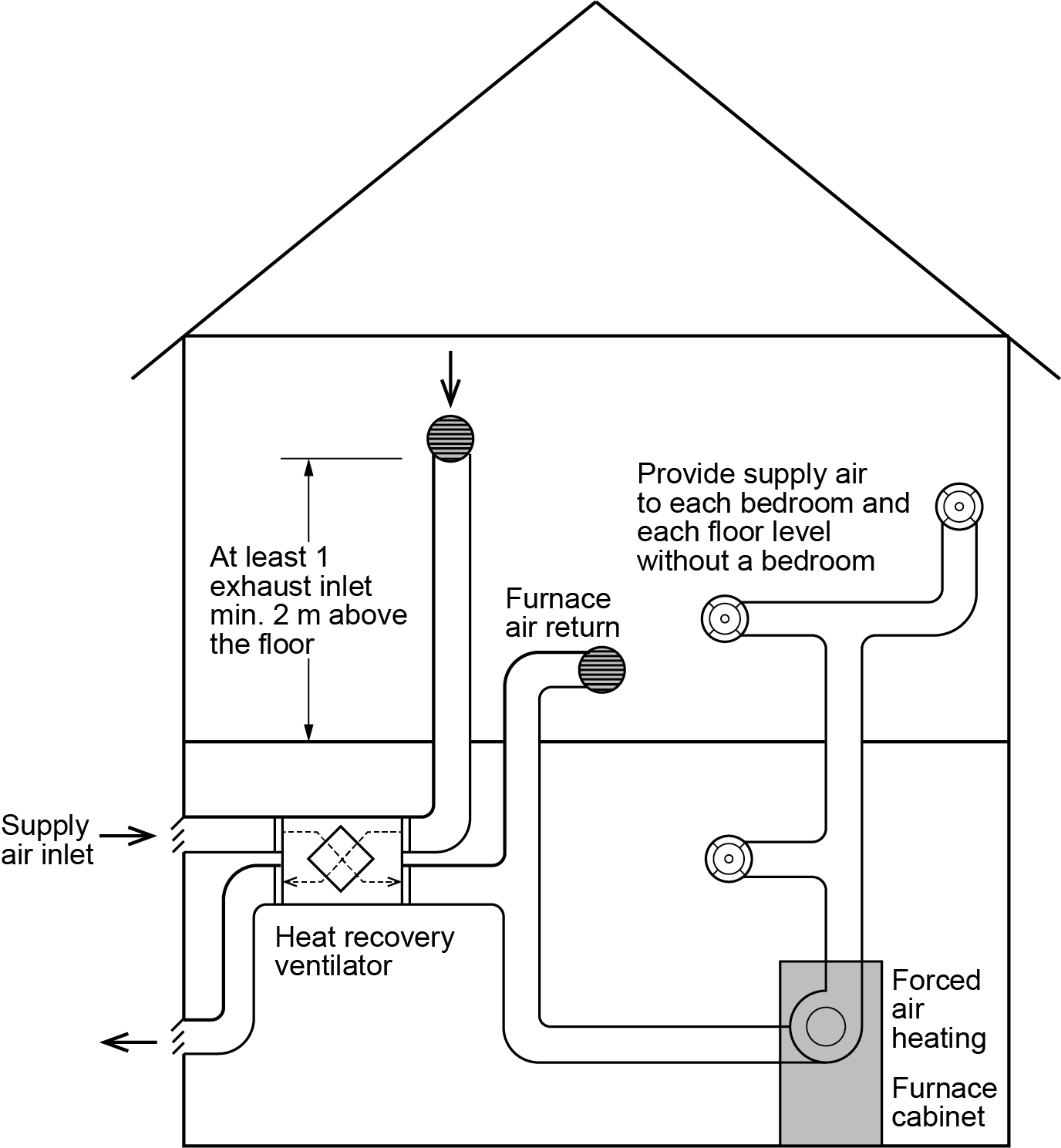
Some residential balanced systems rely upon an exhaust fan to create the building suction needed to draw in outside air. Proper sizing of the return air system and location of the outdoor air inlet connection are critical to ensure that the furnace air-circulating fan does not influence the amount of ventilation air being drawn into the building (Figure 4). If the proportion of cold outside to warm return air is too high, the resulting mixed-air temperature could lead to excessive condensation in the furnace heat exchanger and possible premature failure of the heat exchanger.
Exhaust Equipment
A residential mechanical ventilation system has a principal ventilation exhaust fan with an adequate air-flow rate designed to run continuously. The fan size and air-flow rate are based on the number of bedrooms and the floor area of the dwelling. The principal exhaust fan will create a slightly negative pressure (max negative 5 Pa) that draws ventilation air into the building through the outdoor air inlet (Figure 4).
In buildings where natural draft appliances are installed, care must be taken when selecting exhaust fans; oversized exhaust fans may cause backdrafting of flue gases into indoor areas through appliance venting systems.
Odour-producing and moisture-producing areas in dwelling units, such as kitchens and bathrooms, also require dedicated exhaust fans and ductwork.
Commercial and industrial buildings may have other exhaust equipment, such as dust extractors or kitchen hoods, that need to be interlocked with make-up air equipment to maintain balanced building pressure.
The major disadvantage of the simple system shown in Figure 3 is the heat lost via the exhaust air during the heating season. Any home built to the R-2000 or Energy Star standards must have equipment that will recover the energy from the air being expelled.
Air Exchange Equipment (HRV)
In housing and small buildings, the most common method of recovering heat energy is by preheating the ventilation supply air with the exhaust air using a heat recovery ventilator (HRV). An HRV consists of two fans, creating a balanced air flow, and an in-built “air to air” heat exchanger, which transfers available heat from the exhaust air stream to the cold fresh air supply (Figure 5).
An alternative system, called an energy recovery ventilator (ERV), works in a similar way, but it also transfers some of the moisture from the outgoing airstream into the incoming air to keep the humidity in the home at a constant level. As a general rule, ERV is a better option for an air-conditioned home or a humid climate because it helps keep moisture outside, reducing the load on the air conditioner. HRV is often better when there is no air conditioning or if the building is located in a less humid climate, since it will help keep the humidity down by transferring excess indoor moisture outside.
Combustion Air Requirements
Installers must also consider air consumed by any fuel-burning appliances to maintain a balanced building. The efficient and safe operation of gas-fired appliances relies on an adequate supply of air over and above that required for ventilation or make-up air. Learning Task 2 identified that the gas appliance could use as much a 30 ft3 of total air for each 1,000 BTU/hr of input. There are two common methods of gas appliance air supply:
- Direct vent systems
- Room air systems (non-direct vent)
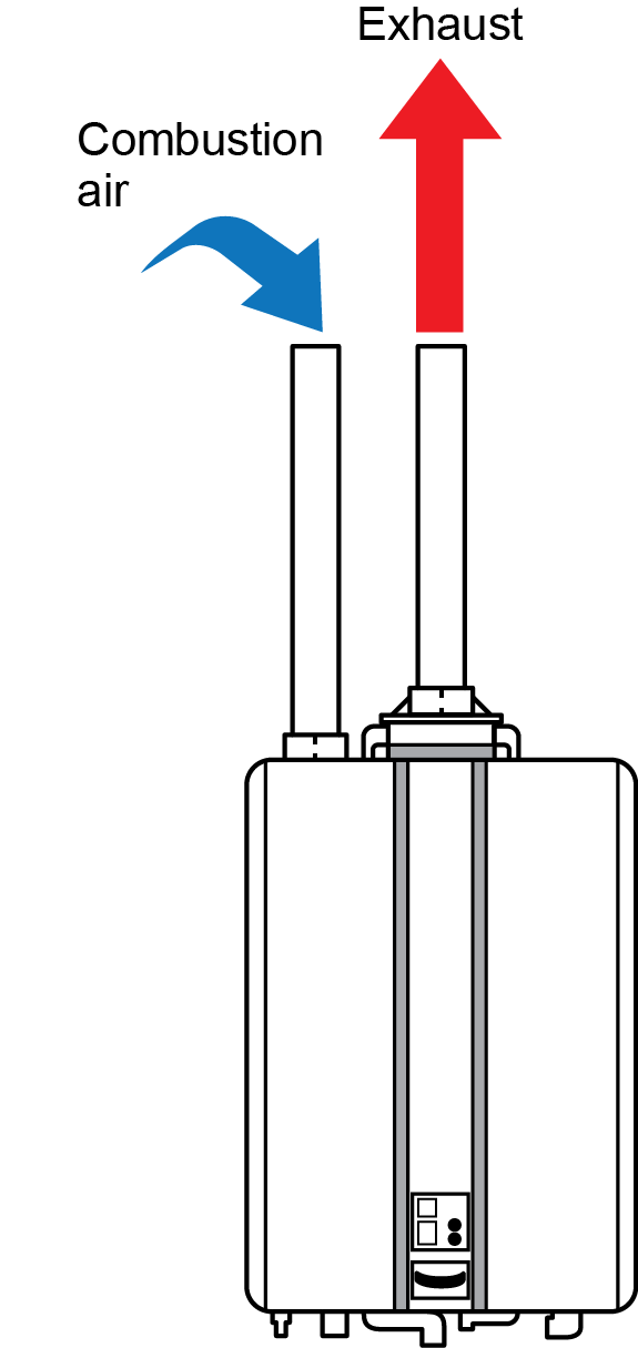
For a direct vent system, all air for the appliance is taken directly from the outside and the flue gas is discharged to the outdoors. Therefore, the direct vent appliance will have no effect on the air balance of the building (Figure 6).
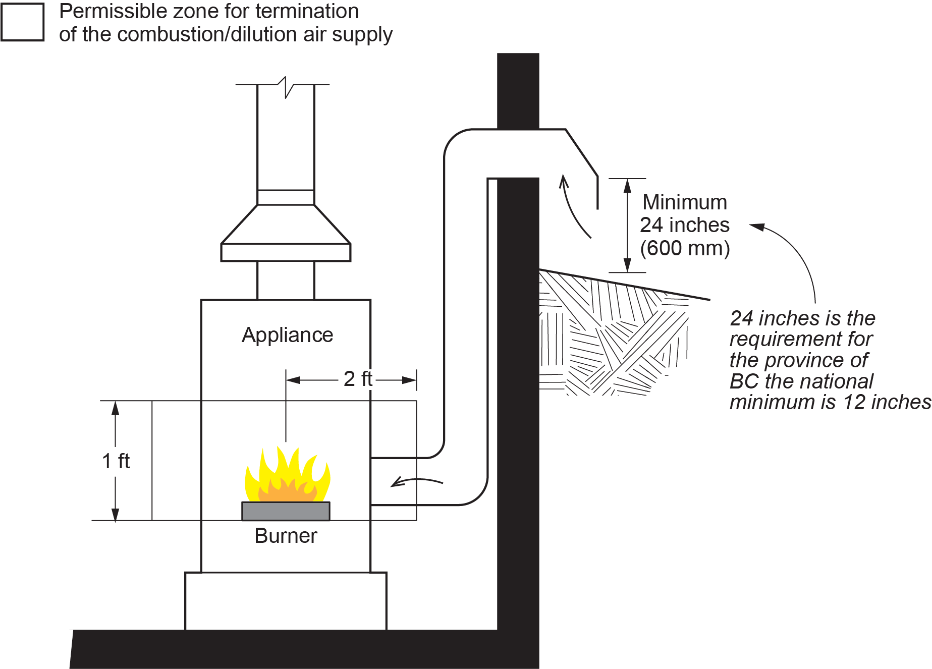
Non–direct vent gas appliances draw all their air supply requirements from the internal room air, which would create a negative pressure in the room if there was not an air supply dedicated to the gas appliance. For gas appliances dependent on room air, the outside air is normally brought to gas appliance burners via a duct, but a hole in the wall can be used if it is located within the same area as that required for the duct (Figure 7). These methods could be referred to as passive air supply compared to a mechanical air supply, such as a fan. If a mechanical air supply is used, it must be properly sized and interlocked with the appliances to shut off the gas in the event of an air supply failure.
The regulations regarding the installation and sizing of passive combustion air supply openings and ducts are detailed in Section 8 of the B149.1 Gas Installation Code.
Whether the air supply duct or pipe is being used for a direct vent or a room air system, if the pipe or duct is too long, it will restrict the flow of air. Fittings also create addition resistance to flow, so pipe should be routed as directly as possible with as few bends as possible.
 Self-Test A-3.4: The Building as a System
Complete Self-Test A-3.4 and check your answers.
If you are using a printed copy, please find Self-Test A-3.4 and Answer Key at the end of this section. If you prefer, you can scan the QR code with your digital device to go directly to the interactive Self-Test.

References
Australian Building Codes Board (ABCB). (2016). Energy efficiency provisions. Canberra: ABCB.
[The] British Columbia Gazette, Part II, Volume 57(17), 175/2014. Crown Publications: King’s Printer for British Columbia. [accessed from the BC Government BC Publications website: Vol. 57 No. 17 — 175/2014 (bcpublications.ca)].
Building and Safety Standards Branch. (2014, September 19). [Figure 1] Information Bulletin No. B14-07: New radon rough in requirements [PDF]. Government of British Columbia. https://www2.gov.bc.ca/assets/gov/farming-natural-resources-and-industry/construction-industry/building-codes-and-standards/bulletins/b14-07_new_radon_rough-in_requirements.pdf
Canadian Standards Association (or CSA Group). (n.d.). https://www.csagroup.org/ and https://www.csagroup.org/store/
Office of Housing and Construction Standards. (2024, March 8). BC codes 2024. Province of British Columbia. https://www2.gov.bc.ca/gov/content/industry/construction-industry/building-codes-standards/bc-codes/2024-bc-codes
N Series: Commercial condensing installation and operation manual (adapted two pipe direct vent diagram) [PDF]. (2019). Rinnai Corporation. https://www.rinnai.ca/
Skilled Trades BC. (2021). Book 1: Fuel gas systems, Heating and cooling systems. Plumber apprenticeship program level 2 book 1 Harmonized. Crown Publications: King’s Printer for British Columbia.
Trades Training BC. (2021). A-3: Air supply for gas appliances. In: Plumber Apprenticeship Program: Level 2. Industry Training Authority, BC.
Media Attributions
All figures are used with permission from Skilled Trades BC (2021) unless otherwise noted.
- Figure 1 Building envelope is by the Australian Building Codes Board (2016) and is used under a CC BY 4.0 license.
- Figure 2 New radon rough in requirements [Information Bulletin] (Figure 1) by Government of BC (2014) is used under Fair Dealing guidelines for educational purposes.
- Figures 4 and 5 have been modified from Figure A-9.32.3.4.(2) and Figure A-9.32.3.4.(3) in The British Columbia Gazette (2014), accessed from the BC Government BC Publications website. These materials contain content derived from information originally made available by the Province of British Columbia at: http://www.bclaws.gov.bc.ca and this information is being used in accordance with the King’s Printer Licence – British Columbia available at: https://www.bclaws.gov.bc.ca/standards/Licence.html. They have not, however, been produced in affiliation with, or with the endorsement of, the Province of British Columbia and THESE MATERIALS ARE NOT AN OFFICIAL VERSION.“
- Figure 6 Adapted diagram by Trades Training BC from Rinnai Corporation (2019) and is used with permission.
A framework made up of different subsystems, including occupants, the building envelope, outside environment, and mechanical/electrical equipment, that work together to manage air, heat, and moisture flow. (Section A-3.4)
The physical boundary between the conditioned and unconditioned parts of a building, which includes the foundation, roof, walls, doors, windows, and insulation, and controls the flow of air, heat, and moisture. (Section A-3.4)
The intentional introduction of outdoor air into a space to control indoor air quality by diluting and displacing indoor pollutants; can also be used for purposes of thermal comfort or dehumidification. (Section A-1.2; Section A-3.4)
Microscopic water molecules that are suspended in air. (Section A-3.1, Section A-3.2, and Section A-3.4)
A mixture of air, water vapour, and pollutants, such as radon, that enters a building through below-grade leaks in the building envelope, potentially affecting indoor air quality. (Section A-3.4)
The unintentional introduction of outside air into a building; also referred to as air leakage. (Section A-3.4)
The air supplied in sufficient quantity to make up for air exhausted to outdoors. (Section A-3.4)
The reverse flow of gas in the flues of fuel-fired appliances that results in the intrusion of combustion by-products into the living space. (Section A-3.4)
The leakage of room air out of the building. (Section A-3.4)
A system that recovers heat from outgoing exhaust air and transfers it to incoming fresh air, helping to improve energy efficiency and indoor air quality. (Figure 5, Section A-3.4)
A ventilation system similar to HRV but also transfers moisture between the outgoing and incoming air streams to maintain balanced humidity levels in the building. (Section A-3.4)
