A-3.3 Gas Appliance Draft
Proper operation of gas appliances requires a draft to move the hot flue gases and air through the combustion chamber, heat exchanger, and venting system. The draft movement can occur naturally (natural draft), or it can be created by a blower (mechanical draft).
For combustion efficiency, the amount and force of the draft must be controlled. A too strong draft will pull in too much combustion air and affect the efficiency of the appliance. A too weak draft will smother the flame and reduce combustion efficiency. Therefore, draft control equipment is an essential part of a venting system.
Natural Draft
When the draft is created naturally, without any mechanical influence (e.g., using a fan), it is referred to as “natural draft.” The natural draft is created because the hot gases from combustion are lighter than the ambient heavy (cool) air and, therefore, move upward and out the vent. The displaced air is replaced by cool outside air coming in.
The movement of air into and out of the buildings, chimneys, and flue-gas vents as a result of air buoyancy is referred to as stack effect or chimney effect. Large temperature differences between the outside air and flue gases can create a strong stack effect in chimneys and vents. The taller the stack, the more draft it creates. There can be limitations on the gains in stack effect created by height. For example, if a stack is overly tall in relation to the heat being sent out of the stack, the flue gases may cool before reaching the top. This condition may result in poor draft.
Natural draft equipment controls the amount of draft by admitting dilution air into a relief opening, breaking the stack effect on the combustion chamber and cooling the hot vent gases.
There are different types of natural draft control equipment, depending on the type of burner and appliance: draft hoods (Figure 1), draft diverters, and barometric dampers.
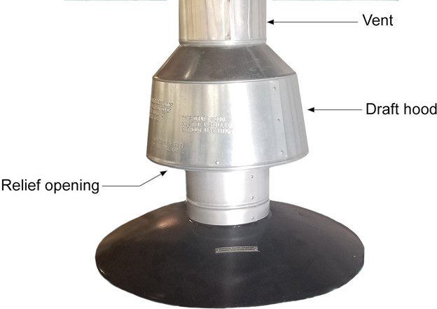
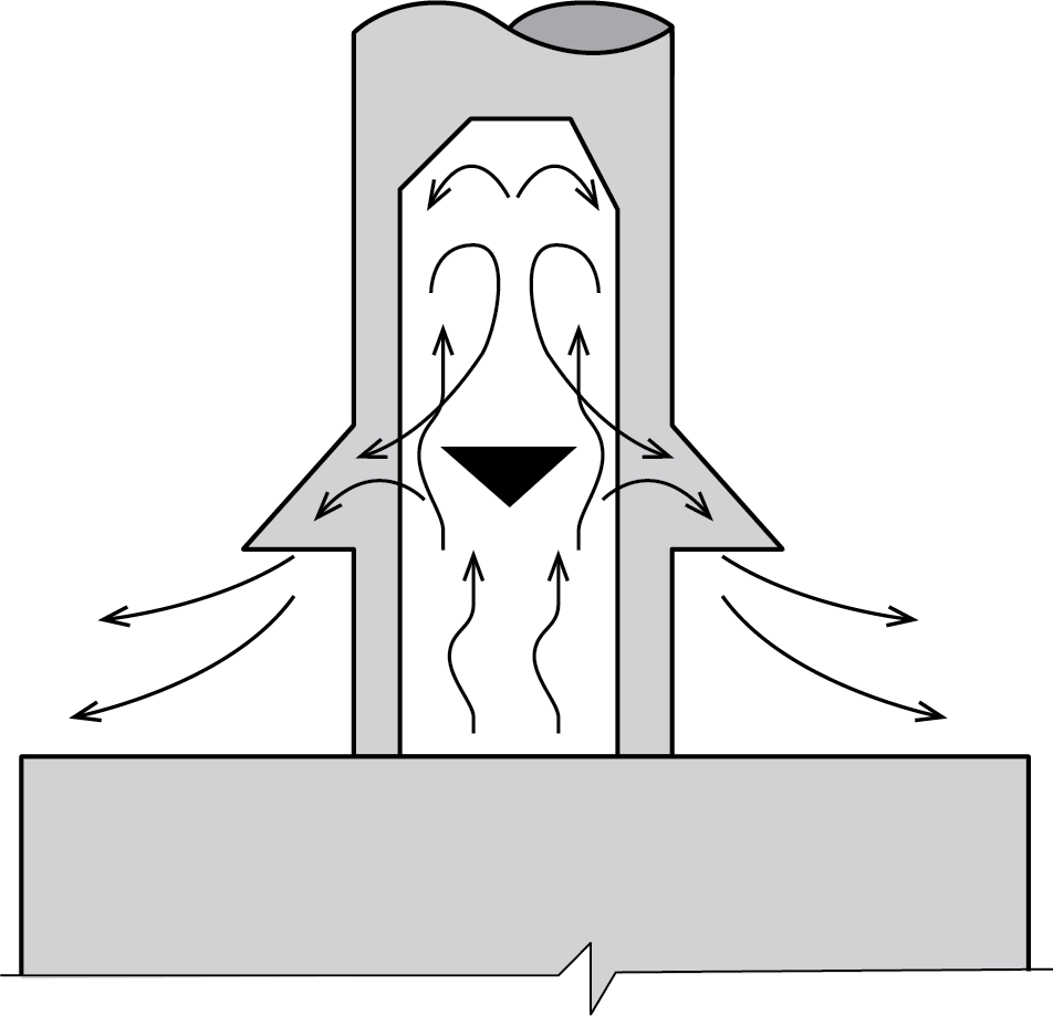
Another purpose of a draft hood is to prevent any downdrafts from entering the combustion chamber of the appliance. The draft hood also allows the draft to spill through the relief opening if the appliance vent is blocked or restricted (Figure 2). For additional protection, the appliance often has a heat-activated safety device called a spill switch that will shut down the burner in the event of flue-gas spillage.
Since the heat inside a natural draft vent system represents the power available to operate the vent, a natural draft vent will not operate properly on high-efficiency appliances. High-efficiency appliances require a mechanical fan or blower to assist in delivering the combustion air and venting the products of combustion.
Mechanical Draft
There are three types of mechanical draft systems:
- Fan-assisted appliances
- Power venters
- Power burners
Fan-Assisted Appliances
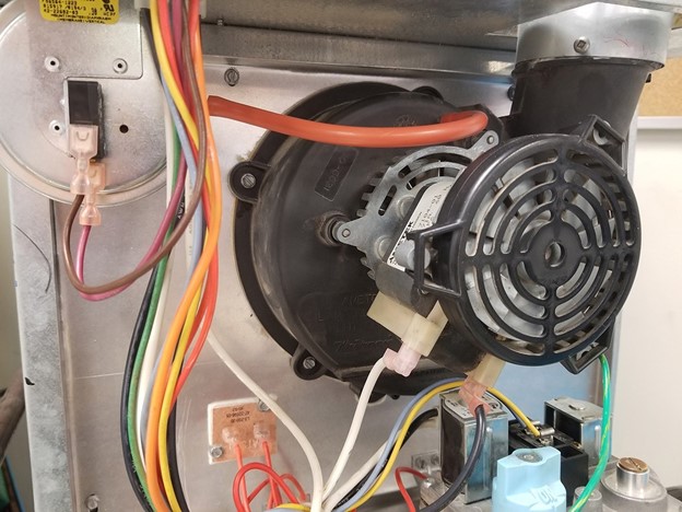
Fan-assisted combustion systems use mechanical means (Figure 3) to either draw or force the products of combustion through the combustion chamber or heat exchanger. This also gives the appliance more accurate control over the air supply, which reduces the amount of excess and dilution air, increasing efficiency. These are mid-efficiency appliances, and the flue products are still hot enough to create a natural draft to remove the flue gases.
Power Venters
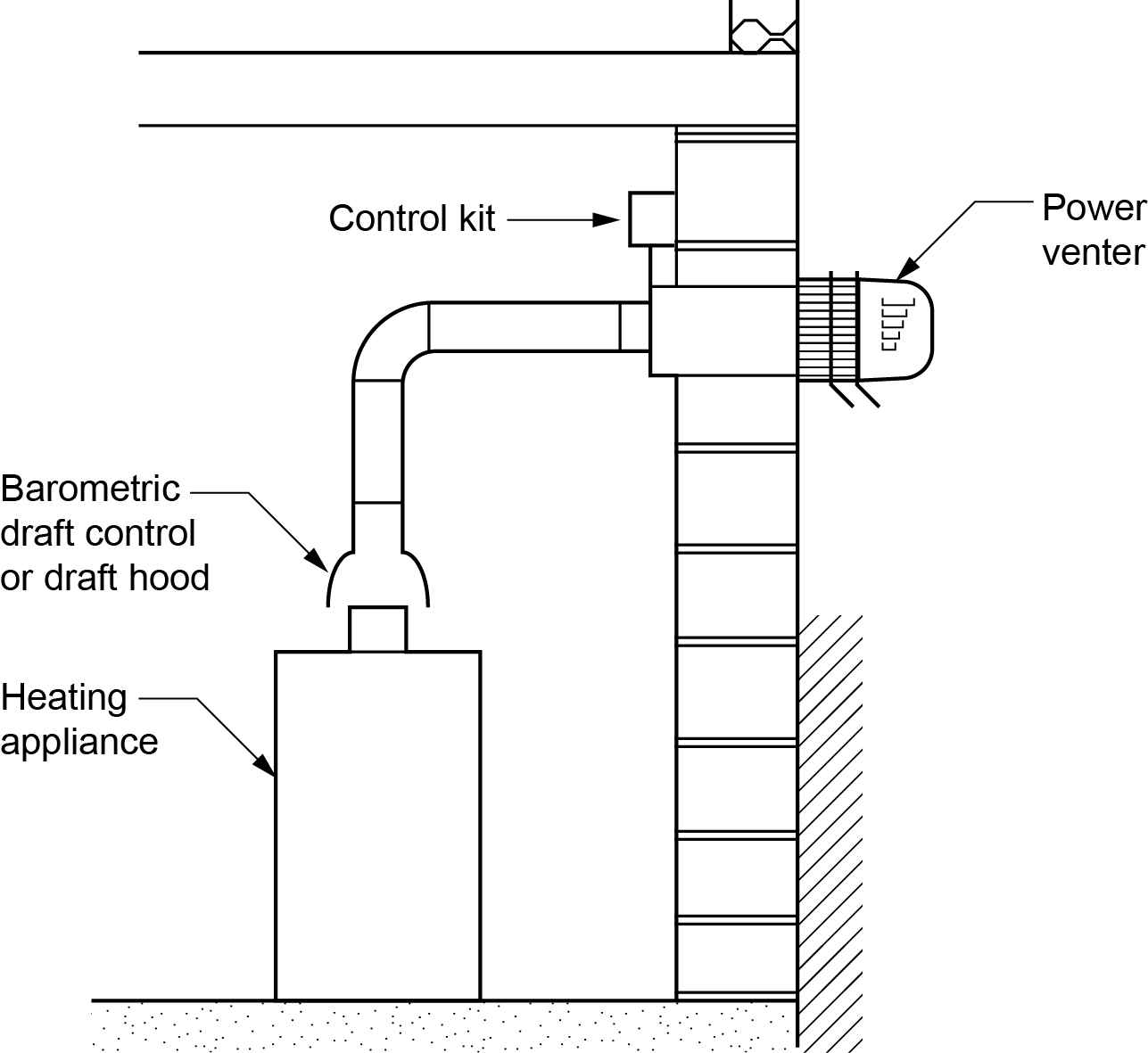
One type of mechanical draft is referred to as power venting. Power venters are sometimes used to overcome particular venting problems, such as extra-long vents, excessive negative pressures, or improper venting design. Power venters are used on natural draft appliances and installed at or near the vent outlet, thus maintaining a negative pressure within the venting system (Figure 4).
Power Burners
Appliances that have mechanical draft burner systems are often referred to as power burners. Power burners generate sufficient pressure to overcome the resistance of the burner, appliance, and venting system. These burners are categorized according to the location of the fan or blower in relation to the combustion chamber, either forced-draft or induced-draft burners.
A forced-draft burner has the fan or blower located upstream of the combustion zone (Figure 5).
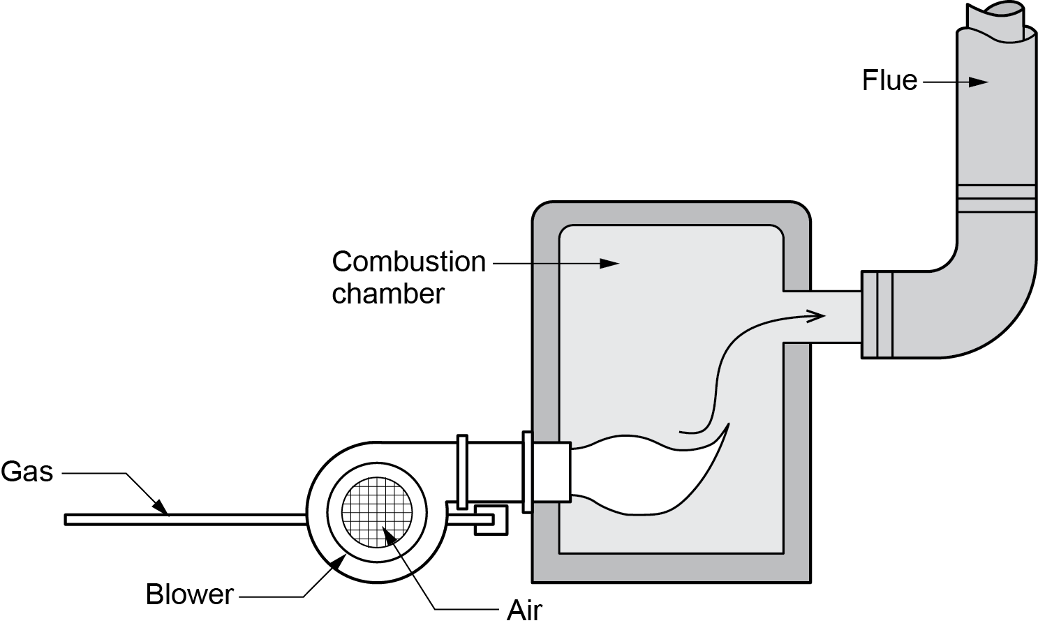
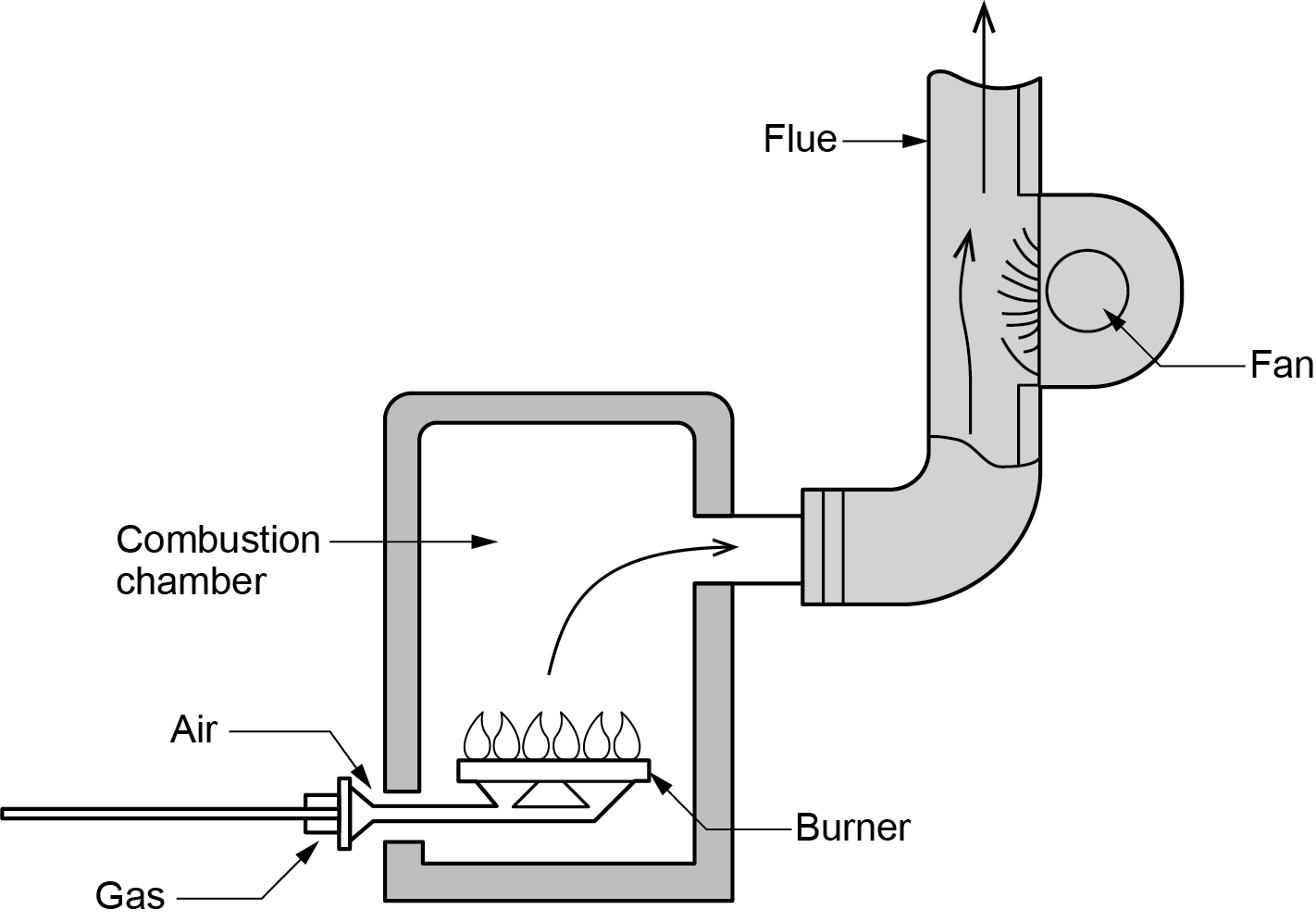
An induced-draft burner uses the mechanical draft produced by a fan located on the downstream (chimney side) of the combustion zone, as shown in Figure 6.
Appliances that rely on mechanical drafts are equipped with an air-proving control interlocked with the burner to confirm the flow of combustion air or flue gas.
Gas Appliance Categories
The type of draft system that is used by a gas appliance greatly affects the efficiency and vent pressure of the appliance, which also has significance to the installation of the appliance.
Therefore, the CSA B149.1 Natural Gas and Installation Code splits appliances into categories based on their vent pressures and efficiencies (flue losses).
Category I
An appliance with a flue loss not less than 17% (not greater than 83% efficiency) that operates with a nonpositive vent static pressure. Example: A standard, non-condensing gas furnace. This type of furnace typically operates at around 80% efficiency and uses a natural draft system where the flue gases are vented through a chimney. The vent pressure is nonpositive, relying on the natural buoyancy of hot gases to rise and exit.
Category II
An appliance with a flue loss less than 17% (greater than 83% efficiency) that operates with a nonpositive vent static pressure. Example: A high-efficiency, non-condensing gas water heater. This appliance is more efficient than Category I, operating at greater than 83% efficiency, but still has a nonpositive vent pressure. It might use a more advanced heat exchanger to extract additional heat from the combustion gases.
Category III
An appliance with a flue loss not less than 17% (not greater than 83% efficiency) that operates with a positive vent static pressure. Example: A tankless gas water heater. This appliance is also non-condensing with an efficiency of around 80-83%, but it requires a power vent system (positive vent static pressure) to expel the combustion gases. The venting system is often sealed and uses a fan to push the gases out, allowing more flexibility in vent placement.
Category IV
An appliance with a flue loss less than 17% (greater than 83% efficiency) that operates with a positive vent static pressure. Example: A condensing gas furnace. These are highly efficient (above 90% efficiency) appliances that condense water vapor from the exhaust gases to extract additional heat. They operate with a positive vent static pressure and often use a PVC vent pipe since the flue gases are cooler.
 Self-Test A-3.3: Gas Appliance Draft
Complete Self-Test A-3.3 and check your answers.
If you are using a printed copy, please find Self-Test A-3.3 and Answer Key at the end of this section. If you prefer, you can scan the QR code with your digital device to go directly to the interactive Self-Test.

References
Canadian Standards Association (or CSA Group). (n.d.). https://www.csagroup.org/ and https://www.csagroup.org/store/
Office of Housing and Construction Standards. (2024, March 8). BC codes 2024. Province of British Columbia. https://www2.gov.bc.ca/gov/content/industry/construction-industry/building-codes-standards/bc-codes/2024-bc-codes
Skilled Trades BC. (2021). Book 1: Fuel gas systems, Heating and cooling systems. Plumber apprenticeship program level 2 book 1 Harmonized. Crown Publications: King’s Printer for British Columbia.
Trades Training BC. (2021). A-3: Air supply for gas appliances. In: Plumber Apprenticeship Program: Level 2. Industry Training Authority, BC.
Media Attributions
All figures are used with permission from Skilled Trades BC (2021) unless otherwise noted.
- Figures 1 & 3 (photos) are by Rod Lidstone and used under a CC BY licence.
A type of draft where the movement of air is created by the buoyancy of hot combustion gases, which are lighter than cooler outside air. (Section A-3.3)
Draft that is created with the help of a mechanical fan or blower to move air and combustion gases, often used in high-efficiency appliances. (Section A-3.3)
The phenomenon where hot air rises due to its lower density, creating a natural flow of air into and out of buildings, chimneys, and vents. (Section A-3.3)
A device that helps control draft in natural draft systems, preventing downdrafts and allowing for safe venting even if the vent is blocked. (Figure 1, Section A-3.3)
A device used in heating systems to help control the airflow going in and out of the chimney. It automatically adjusts to make sure the right amount of air is flowing through the system, which helps the appliance burn fuel more efficiently. This keeps the system working properly and prevents problems like too much smoke or wasted energy. (Section A-3.3)
A mechanical draft system used to assist venting in natural draft appliances, often used to overcome venting challenges like excessive negative pressure. (Section A-3.3)
A burner with mechanical draft that generates sufficient pressure to overcome resistance in the combustion chamber, appliance, and venting system. (Section A-3.3)
A type of power burner where the fan or blower is located downstream of the combustion zone, creating draft by drawing gases out of the combustion chamber. (Section A-3.3)
A type of power burner where the fan or blower is located upstream of the combustion zone to force air into the combustion chamber. (Section A-3.3)
(CSA B149.1); The different types of natural gas appliances classified based on their efficiency and the pressure of their venting system. The classification helps determine how the appliance operates and how the combustion gases are vented. There are four main categories: Category I, Category II, Category III, and Category IV, with each category indicating a specific range of efficiency and venting pressure. (Section A-3.3)
