A-1.2 Types of Gas Fired Appliances
As a gasfitter, you may be required to install and service many different gas-fired appliances, some simple, some complex, some vented, and some non-vented. This chapter will familiarize you with some of the most common appliances encountered and provide a brief overview of some of their operational characteristics. In addition to the manufacturers’ installation instructions, refer to Section 7 of the CSA B149 Gas Installation Code for general installation requirements.
Gas Ranges and Commercial Cooking Equipment
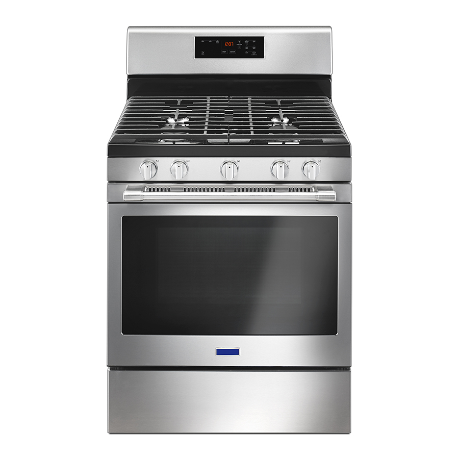
Cooking with gas has the benefit of instant heat and immediate cool down. Numerous styles of gas ranges, types of ignition systems, and temperature controls are used. The most common domestic gas ranges are the zero-clearance, free-standing models (Figure 1). They are self-contained, self-supported, and equipped with top burners and an oven. A range must not be installed in a bedroom because it might produce carbon monoxide. However, a range may be installed in a bed-sitting room if the range is not used as a space heating appliance.
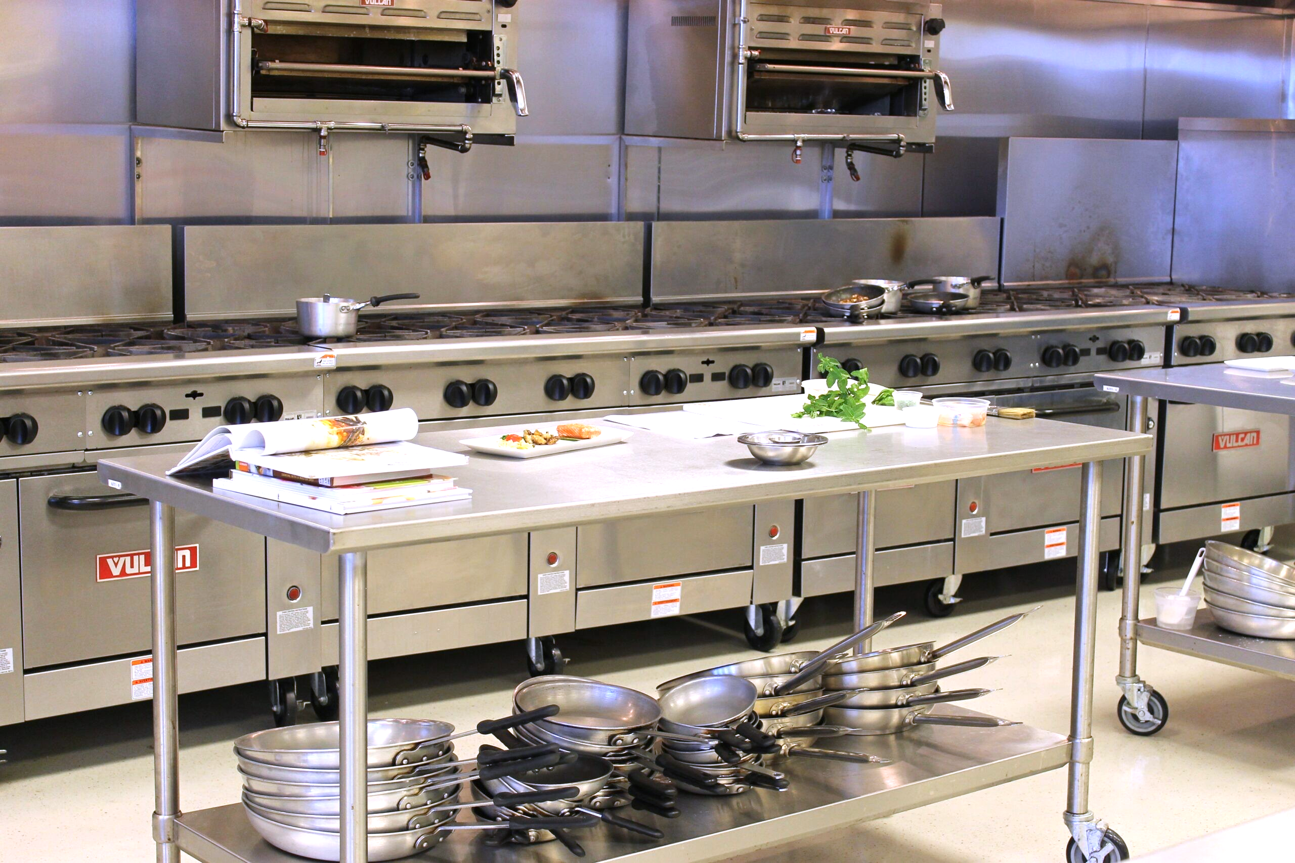
Commercial restaurant cooking equipment often comprises separate units, designed to be installed in batteries (Figure 2). They can include ovens, various types of cooktops, and deep fat fryers. Cooktops can be equipped as all open burners, all griddle, or a combination of burners and griddles.
The following factors must be considered when installing a gas range:
- Specific installation requirements, including manufacturer’s instructions
- Leveling the range
- Anti-tipping devices
- Restraining device for commercial cooking appliances on wheels
- Clearance to combustibles
Specific installation requirements, such as proper positioning and adequate space for the appliance, include the following:
- Compliance with clearance requirements to combustibles, in accordance with manufacturer’s instructions, the rating plate, and applicable codes
- Access for cleaning, repairs, and servicing
- Proper distance to venting hoods, flues, or ductwork, if installed
- Proper positioning with respect to adjacent cabinets, countertops, and other appliances
Gas-Fired Refrigerators and Freezers
Gas-fired refrigerators are popular for off-grid applications. They operate on an absorption principle in which heat from a gas flame provides the energy needed to drive the cooling process. Thus, the system silently provides the mechanical circulation for the refrigerant, without a compressor. Non-vented models for use in areas such as shops, sheds, screened porches, and other unoccupied areas come equipped with a carbon monoxide alarm and a safety shut-off.
There are four basic components to an absorption refrigerator (Figure 3):
- Generator (boiler)
- Condenser
- Evaporator
- Absorber
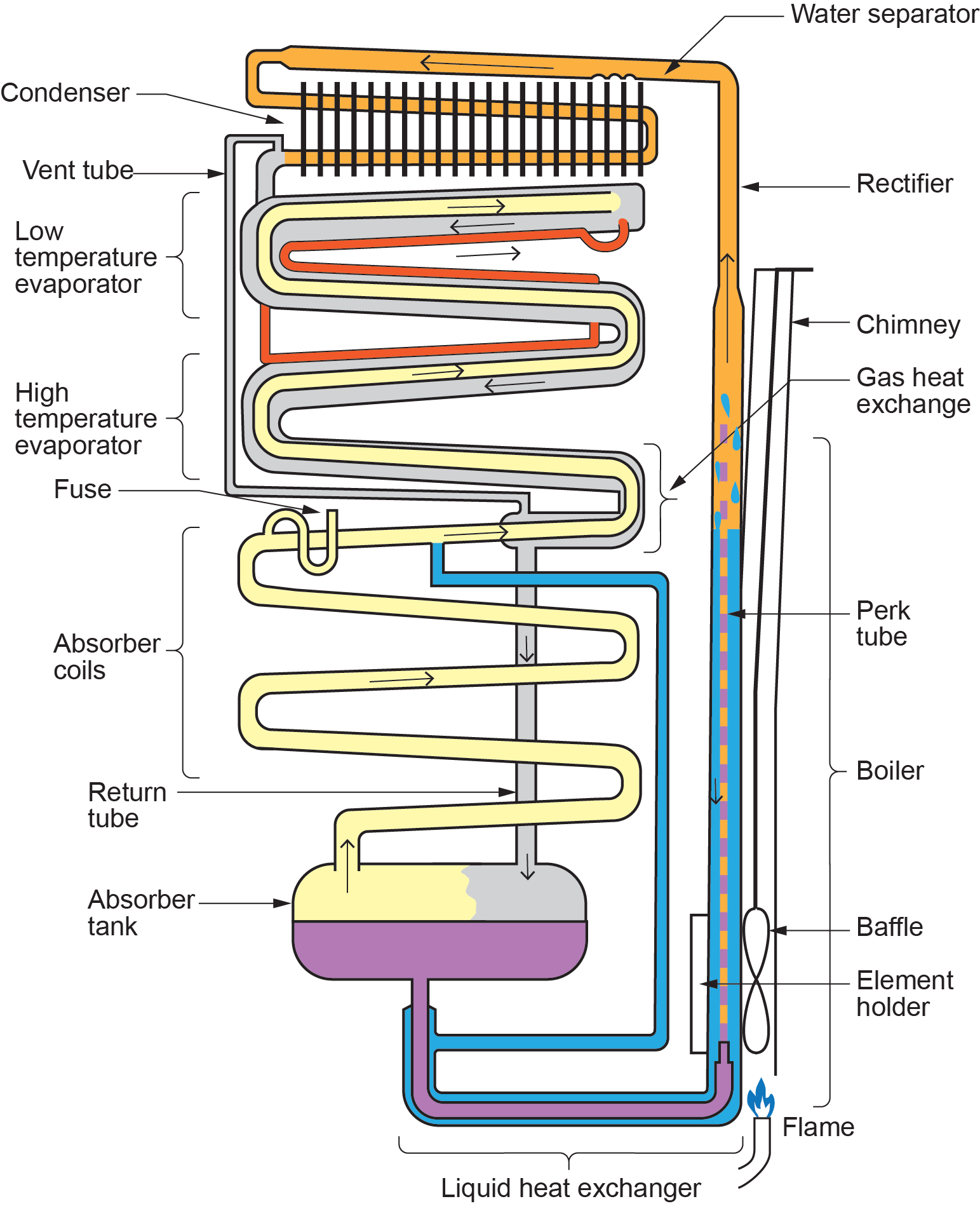
Briefly described, ammonia is liquefied in the finned condenser coil located at the top rear of the refrigerator. The liquid ammonia then flows into the evaporator inside the freezer section, where it is exposed to a circulating flow of hydrogen gas. This exposure causes the ammonia to evaporate, creating a cooling effect in the freezer.
One of the most important factors for trouble-free operation is proper venting behind the refrigerator. Since the refrigerator works on the principle of absorbing and releasing heat, it is of utmost importance to have proper air circulation.
Since refrigerator burners are tucked away in an enclosed space, the burners must be supplied with sufficient combustion air, and exhaust gases must be vented outside. Direct vent fridges need to be located/installed on an outside wall.
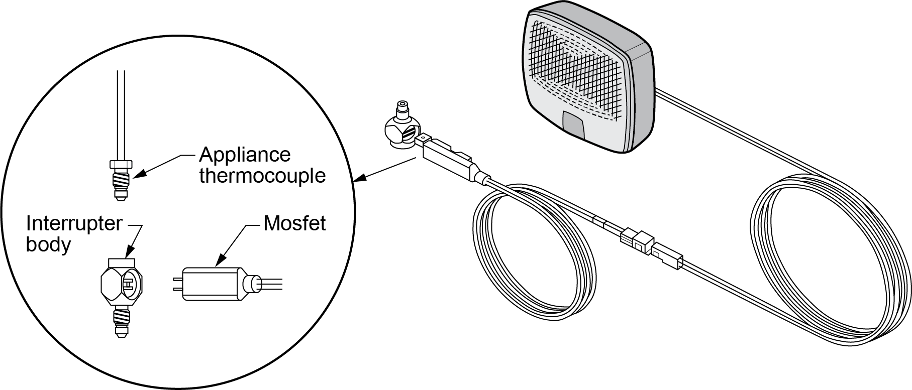
Some models of gas refrigerators come with a carbon monoxide (CO) sensor, which may also have a safety shut-off device. After locating and mounting the detector, connect it to the appliance. Some appliances have a matching plug on the lower back of fridge. Other fridges may require the use of a thermocouple interrupter body and MOSFET adapter (Figure 4).
For units supplied with a CO sensor, manufacturers recommend testing the alarm operation at least once per week during use or if the appliance has been turned off for a period of time.
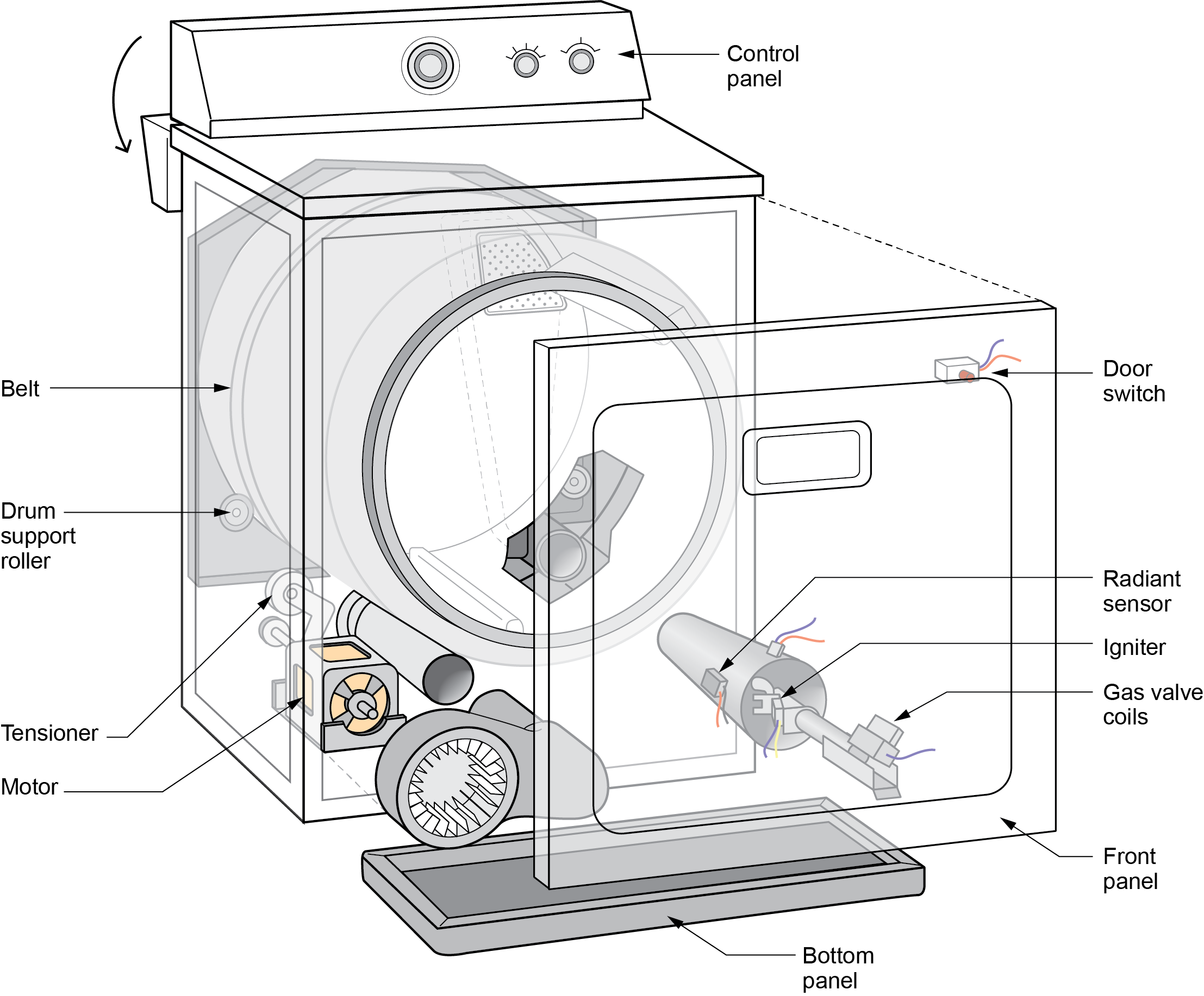
Clothes Dryers
A gas-fired clothes dryer (Figure 5) looks and operates very similar to an electric tumble dryer. Tumble dryers continuously draw in the ambient air around them and heat it before passing it through the tumbler. The resulting hot, humid air is vented outside with a moisture exhaust duct, which makes room for more air to continue the drying process.
A gas burner generates the heat in a gas dryer, but electricity still powers the motors within the appliance. As such, gas dryers require both a 110-volt electrical outlet and a gas hookup.
For gas units, in addition to removing the moisture that evaporates from the wet clothing, the moisture exhaust duct vents the products of combustion that are mixed with the moist air. The code sets specific requirements for the placing and type of moisture exhaust ducts that may be used.
Space Heaters, Fireplaces, and Decorative Appliances
For certain spaces, it is not realistic to put in a central furnace or boiler system, so a space heater or gas fireplace may better meet the needs. Likewise, if a person wishes simply to add ambience or atmosphere to a room, a decorative appliance will do the job.
Space Heaters
There are many types of gas space heaters available. To ensure satisfied customers, a gasfitter must be familiar with the capabilities and uses of different space heaters. What follows are some of the more common types of space heaters.
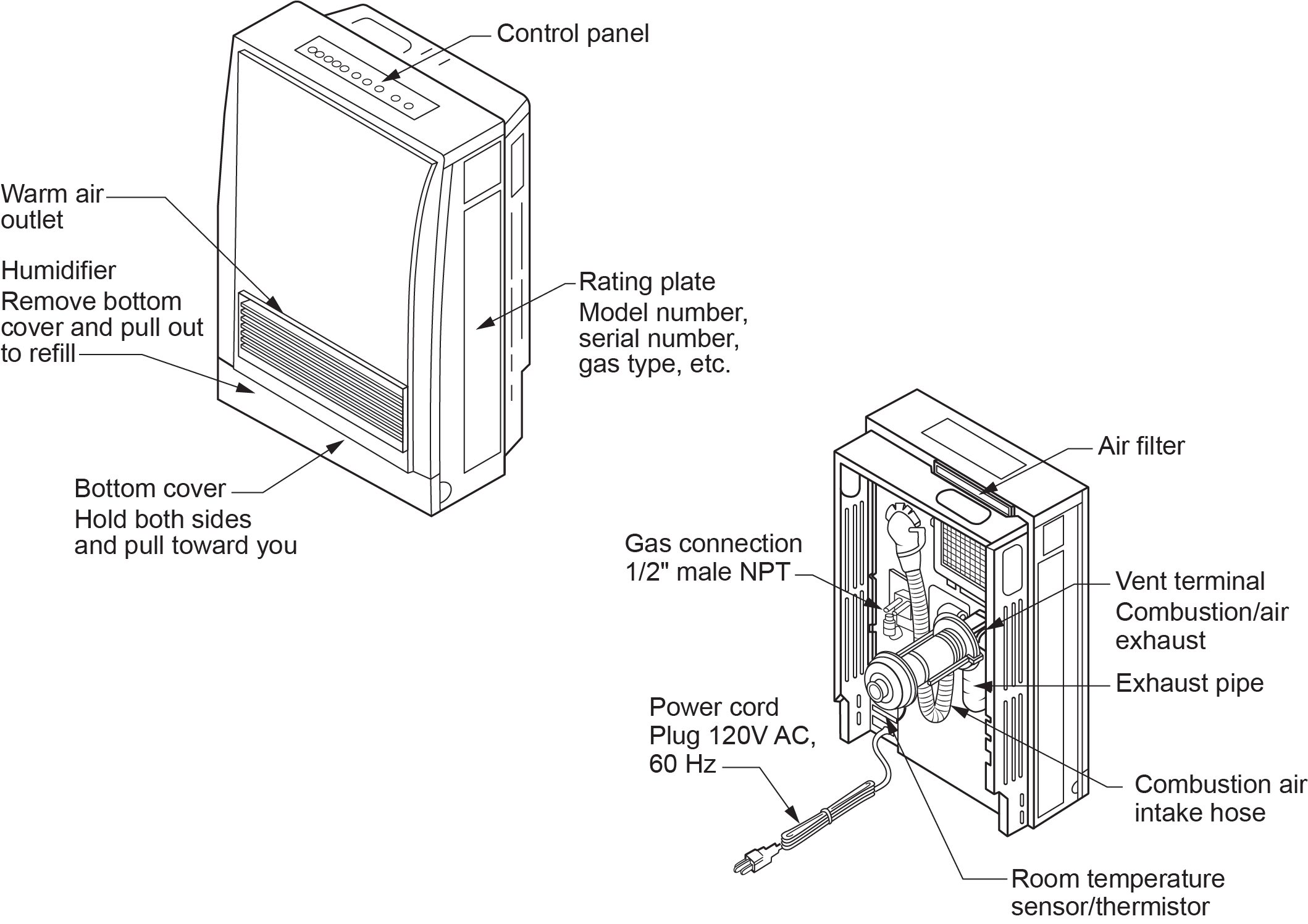
Room Heaters
A room space heater is a self-contained, free-standing, non-recessed, gas-burning appliance that furnishes direct warm air to the space in which it is installed without ducting (Figure 6).
It converts the fuel energy to convection and radiant heat by transferring heat from flue gases to the circulating air through a heat exchanger. The heated air can be distributed through natural convection or with a circulating air blower.
Modern room heaters, like the unit shown in Figure 6, are often coaxial direct vent units mounted onto the interior surface of an outside wall.
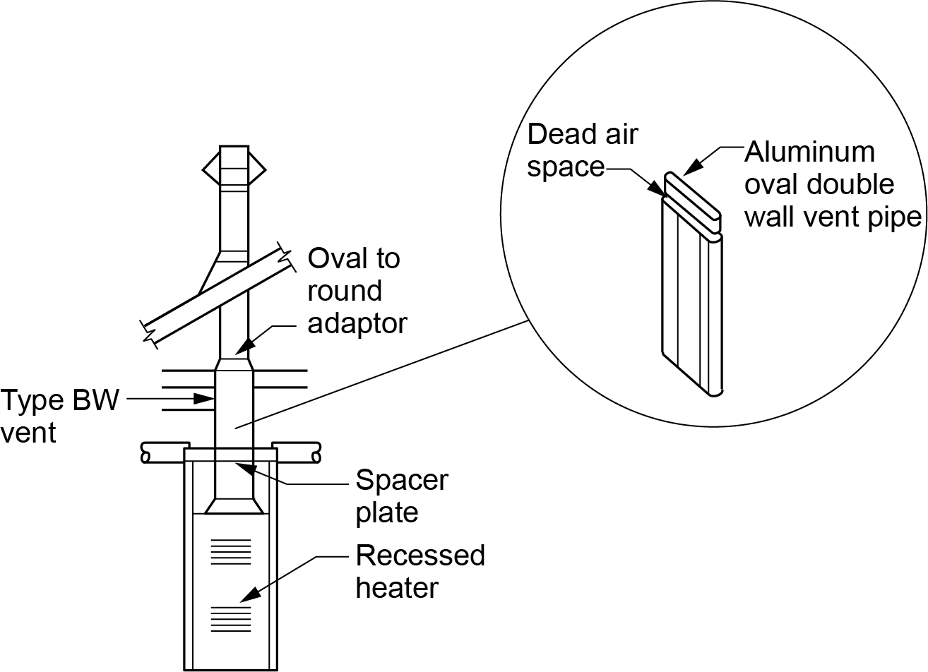
Recessed Wall Furnace
The modern use of the term “gas wall heater” typically refers to the previously shown type of room heaters, which are mounted against the wall. Another wall-mounted type of room heater is the recessed wall furnace designed to fit in a wall cavity. These are still sold but are not as commonly used for new installations, as they are natural draft units that require a special oval vent (BW vent) configuration designed to fit inside a stud wall (Figure 7).
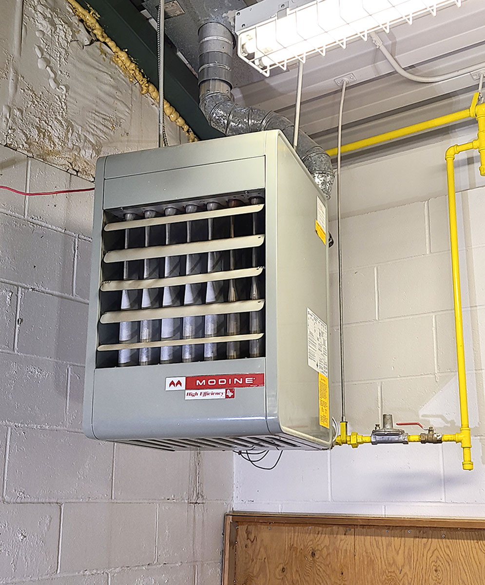
Unit Heaters
Unit heaters are self-contained, ductless, vented, fan-type commercial space heaters that are typically suspended in garages or shop areas (Figure 8). There are a variety of gas fired unit heaters for various applications. The different characteristics are defined by some of the component options, such as type of airflow fan, venting, combustion air supply, and efficiency.
Infrared Heaters
Infrared heaters are typically used to heat large open areas, such as outdoor eating spaces, arenas, and warehouses, where spot heating is required. They are suspended from beams or joists and radiate heat toward the ground.
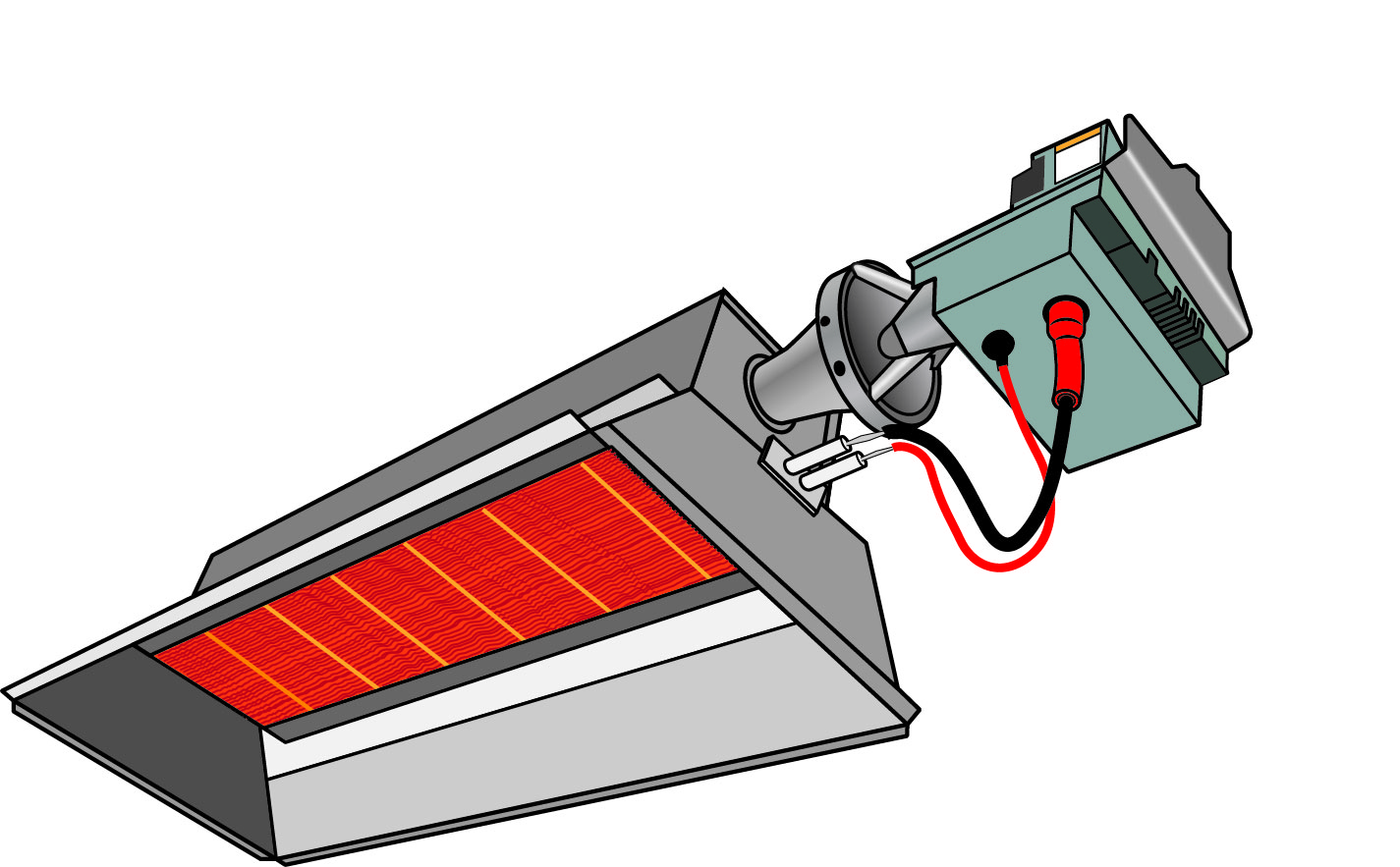
High-Intensity Infrared Heaters
High-intensity infrared heaters have burners made of porous material, such as ceramic or a metallic screen (Figure 9). A combustible mixture of gas and air flows through the refractory material, at which point the gas ignites. The surface temperature may rise as high as 980°C (1,800°F), which helps retain the flame on the surface, increasing radiating efficiency. Because high-intensity units are non-vented, there usage is quite restricted.
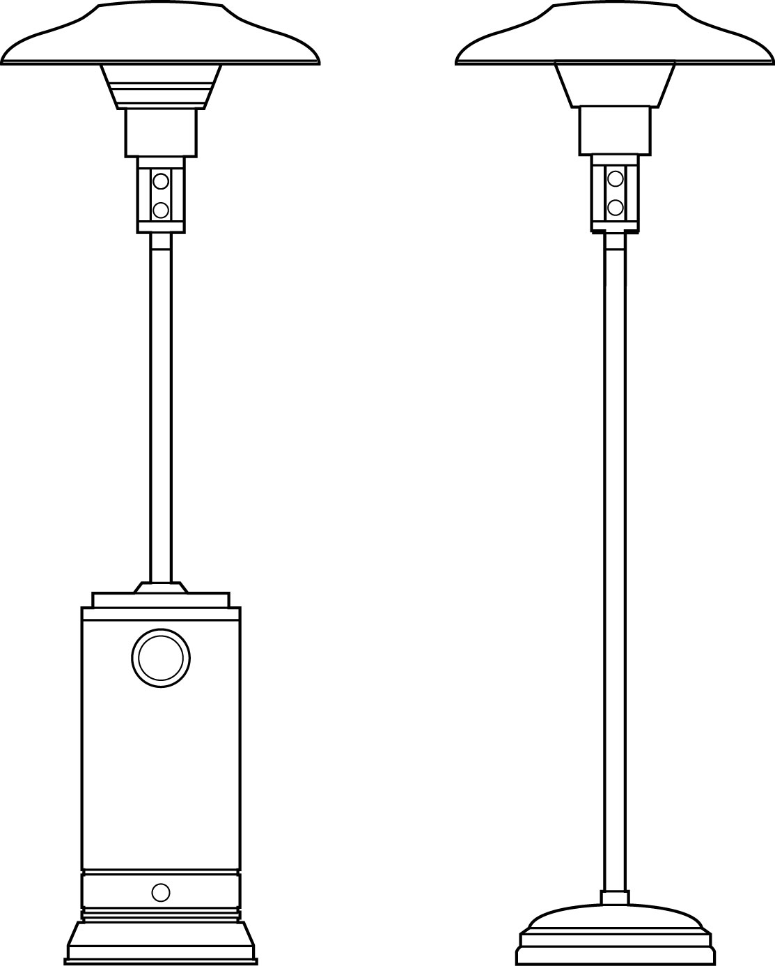
Parasol heaters are another style of high-intensity gas unit heater designed specifically for patio areas. Units can be free-standing or permanent post installations (Figure 10).
Low-Intensity Infrared Heaters
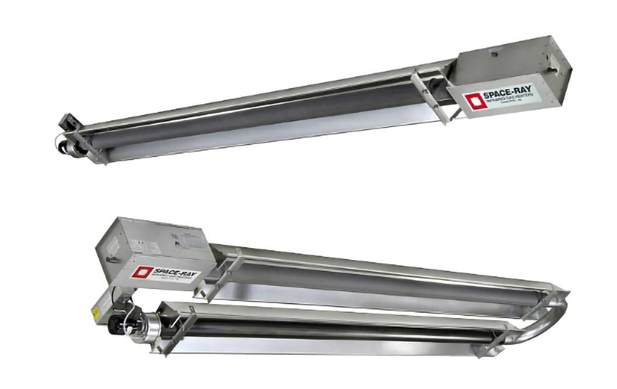
In low-intensity infrared heaters (tube heaters), combustion occurs in tubes or panels made of metal or ceramic. The tubes radiate heat to reflectors, which in turn direct the heat source to the floor. The surface temperature may be as high as 650°C (1,200°F), and the units are generally vented to the atmosphere. There are straight and u-shaped styles. As the length increases, the input will also increase (Figure 11).
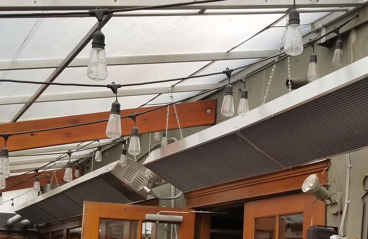
Emmitt guards or screens are installed to cover the exposed tubes for safety or cosmetic reasons, as shown in Figure 12.
Gas Fireplaces
There are two categories of gas fireplaces: decorative or heating. Decorative appliances are not designed for efficiency or intended for use as heaters. They are used to add atmosphere and ambience to a room and typically do not have a thermostat. Heating gas fireplaces, also known as vented gas fireplace heaters, have higher efficiency ratings (minimum 50%) and additional temperature controls. All units must have a direct vent configuration, unless it is marked for replacement use only.
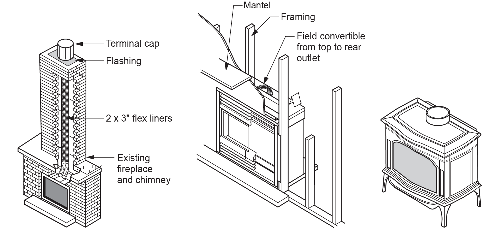
For both categories, there are three common gas fireplace configurations (Figure 13):
- Gas fireplace inserts: used to convert existing wood-burning masonry or factory-built fireplaces to gas.
- Zero-clearance gas fireplaces: used in installations where there is no existing fireplace. They have a lot of installation location flexibility because they can be built into a wall, a corner, a peninsula or even an island in the home. This involves building the space and framing in the unit.
- Free-standing gas fireplaces: typically resemble wood-burning stoves and, therefore, are often referred to as gas stoves. Some units may require the installation of insulating materials to protect combustible walls and floors from high temperatures.

A type of gas fireplace to avoid in Canadian housing is the “vent-free gas fireplace,” which is available in the United States. These units do not vent to the outdoors; all the combustion gases are released directly into the house. Even though most of these fireplaces are equipped with an oxygen depletion sensor, they can still cause serious indoor air quality problems, particularly in airtight Canadian homes and are not approved for use in Canada.
Each fireplace will have some unique installation, operation, and maintenance procedures. Be sure to follow the manufacturer’s instructions carefully to ensure proper clearances from combustibles and that approved venting materials are used.
The core component of the gas fireplace is called the engine. To maximize the number of exterior styles options, manufacturers will often have many different exterior casings for the same engine. The amount of installer onsite assembly will vary with different types of fireplaces. The optional features that have been ordered will also affect the installation. For example, some models may have a circulation blower, which requires a separate 120 VAC power outlet.
The installation of the venting system is one of the most important aspects of the gas fireplace installation. Manufacturers design fireplaces to give the maximum amount of installation flexibility, which often means multiple venting options for a single model such as:
- Direct vent coaxial top exit, horizontal or vertical termination (Figure 14)
- Direct vent coaxial rear exit, horizontal or vertical termination (Figure 15)
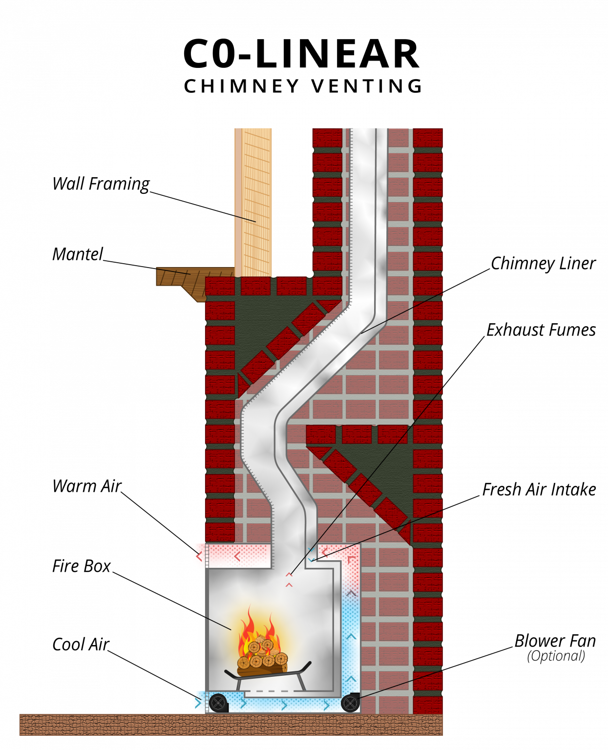
- Direct vent collinear top exit, vertical termination (Figure 16)
- Direct vent power vent (Figure 17)
- Natural draft B-vent (Figure 18)
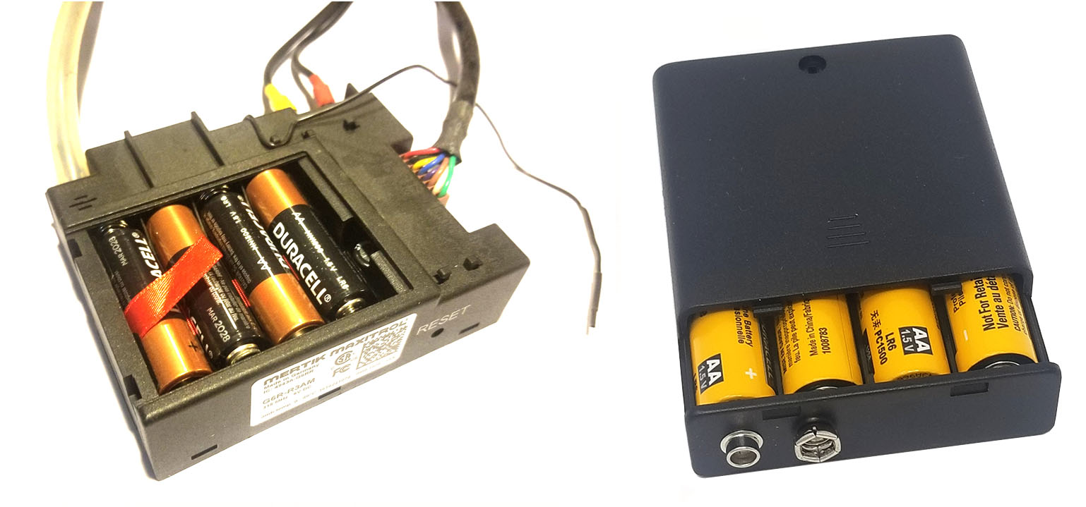
Often homeowners like to use gas fireplaces as an auxiliary backup heater in the event of a power outage. For those applications, a continuous pilot system used to be the best choice because those units did not rely on electricity for their burner operation. To meet efficiency standards, continuous pilot fireplaces are being phased out by DC voltage electronic ignition systems, which use common dry cell batteries as the backup or main power source. This gives intermittent pilot models the same auxiliary heat benefit as the continuous pilot models. The receiver/control module has a compartment to install four AA batteries or a separate battery holder that plugs into the module (Figure 19).
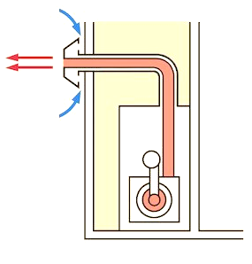
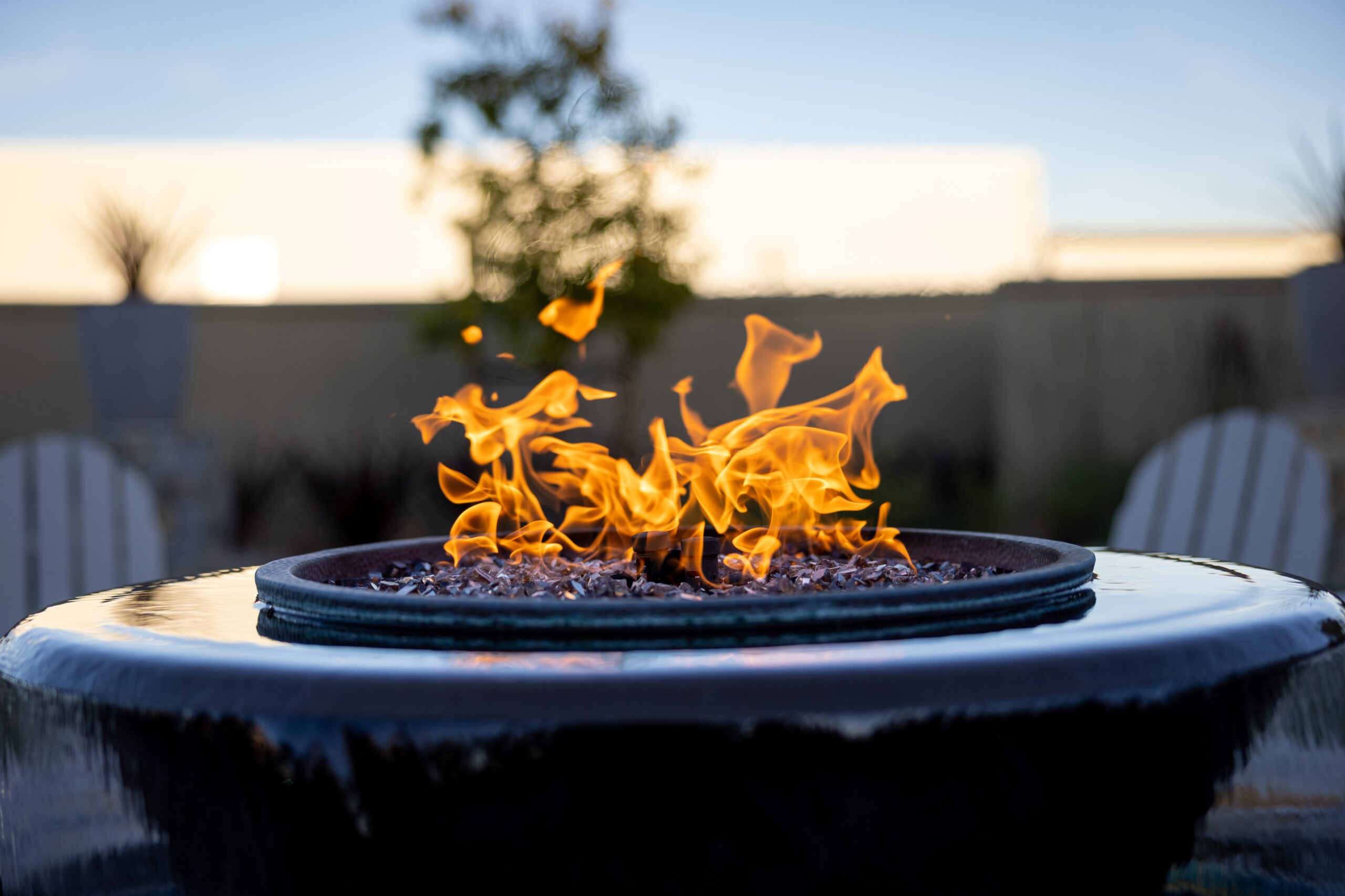
Firepits
Firepits are used as a focal point for outdoor entertaining. They are a decorative appliance that provides heat to the surrounding area. Typically, a firepit consists of concrete blocks placed on a base assembly (Figure 20). The burner is located at the bottom of the pit, and a grate assembly, covered with lava rock, is placed above the burner.
Water Heaters
Water heaters are used primarily to heat domestic water for bathing, cooking, cleaning clothes, washing dishes, and more. Some water heaters now provide the option of hydronic heating along with their domestic duties and are called “combination units.”
There are two basic design categories:
- Under-fired storage
- On-demand (tankless)
Storage Type
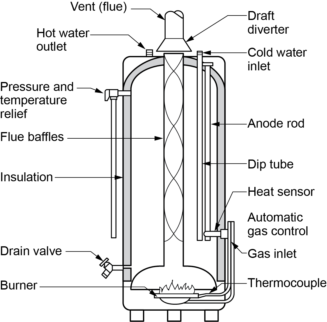
Automatic, under-fired storage tank heaters are the most common type of gas-fired water heater. In this type of water heater, the burner, storage tank, outer jacket, insulation, and controls are combined into one unit (Figure 21).
The ignition source for the burner may be a constant (standing) pilot, intermittent pilot, or direct ignition.
The products of combustion from the burner heat the bottom of the tank, then travel through a central pipe heat exchanger to the flue outlet. Within the heat exchanger is a flue baffle that slows down the vent gases to better take advantage of the heat. Incoming cold water is directed to the bottom of the tank near the burner through a pipe called a “dip tube.”
Gas storage water heaters are available with one of the following venting systems to best suit the installation: natural draft, direct vent, power vent, or power direct vent.
All newly installed 30- to 50-gallon residential gas storage water heaters with firing rates up to 75,000 BTUs/h must be equipped with a flammable vapour ignition resistant (FVIR) combustion chamber. Because the air intake is very low to the ground, the FVIR system is designed to prevent accidental or unintended ignition of flammable vapours outside of the combustion chamber. This is particularly applicable in garages, where spilled gasoline or other combustible fluids are prevalent.
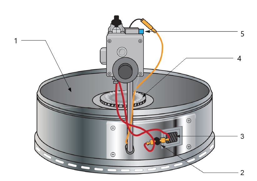
The components of the FVIR burner assembly shown in Figure 22 are:
- Stainless steel flame arrestor plate: provides a one-way path for air to travel through
- Resettable thermal cut-off: shuts down the gas flow to the pilot and burner if flammable vapours enter the combustion chamber and ignite
- Sight glass: provides view of the operation of the pilot and burner in the sealed chamber
- Upshot multiport burner
- Piezo igniter: ignites the pilot burner in the sealed chamber
Tankless Type
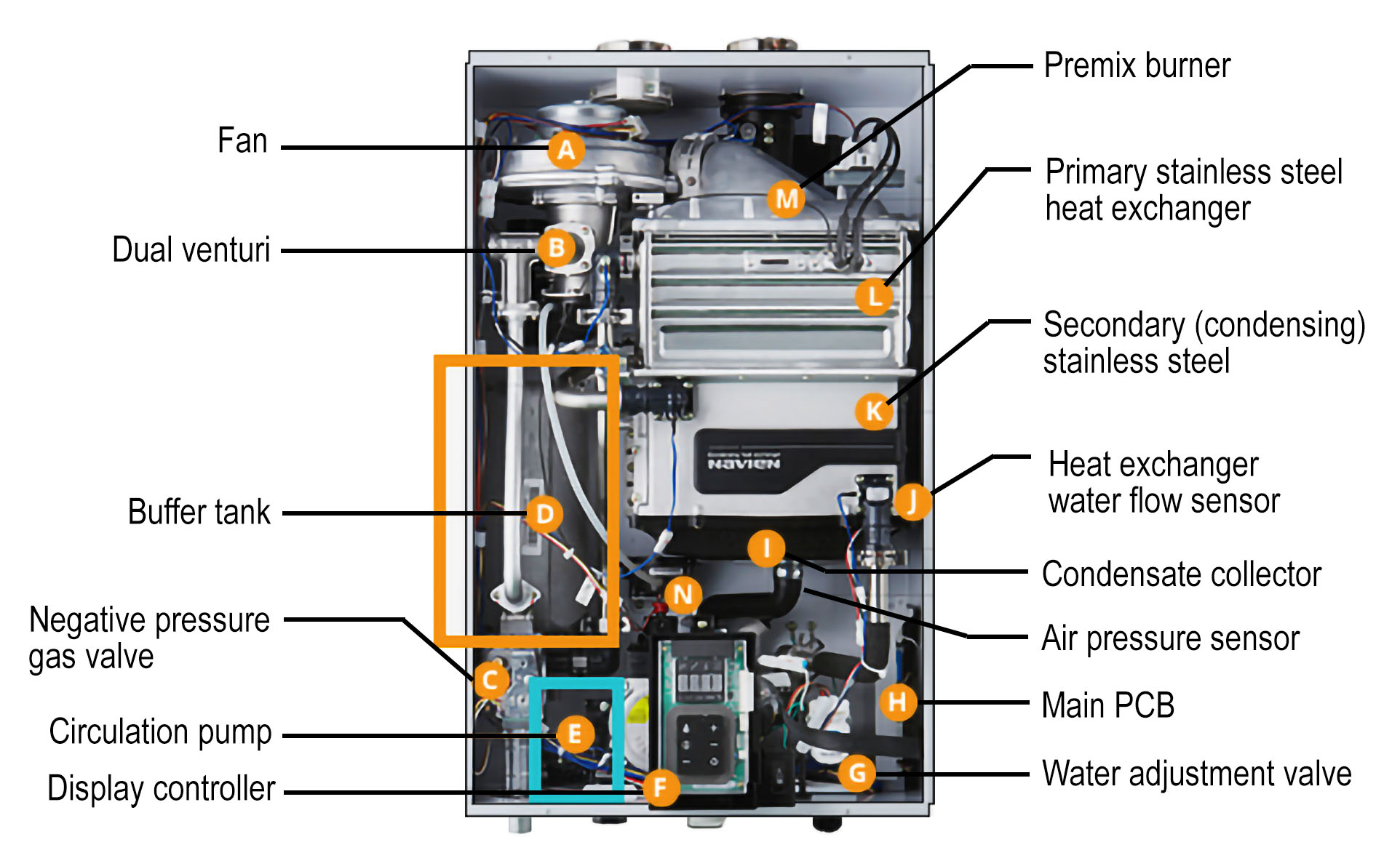
Instead of storing the heated water, tankless water heaters heat the water as it flows through the heat exchanger coils and delivers the heated water to the distribution piping on demand from the fixtures (Figure 23). The amount of hot water that tankless heaters can produce is expressed in gallons per minute, or litres per minute, which varies depending on the burner input and the difference in temperature between the incoming cold supply and the hot water delivery temperature setting. Tankless heaters have the advantage that, if they are sized correctly within their rated capacity (GPM) flow rate, they will deliver a constant supply of hot water.
The size of gas pipe to a tankless water heater is typically larger than that required for an under-fired storage water heater. This is necessary because the tankless style has a very high firing rate (normally ranging from 100,000 BTU/h to 200,000 BTU/h for residential units) compared to under-fired storage water heaters (normally 35,000 Btu/h to 80,000 BTU/h).
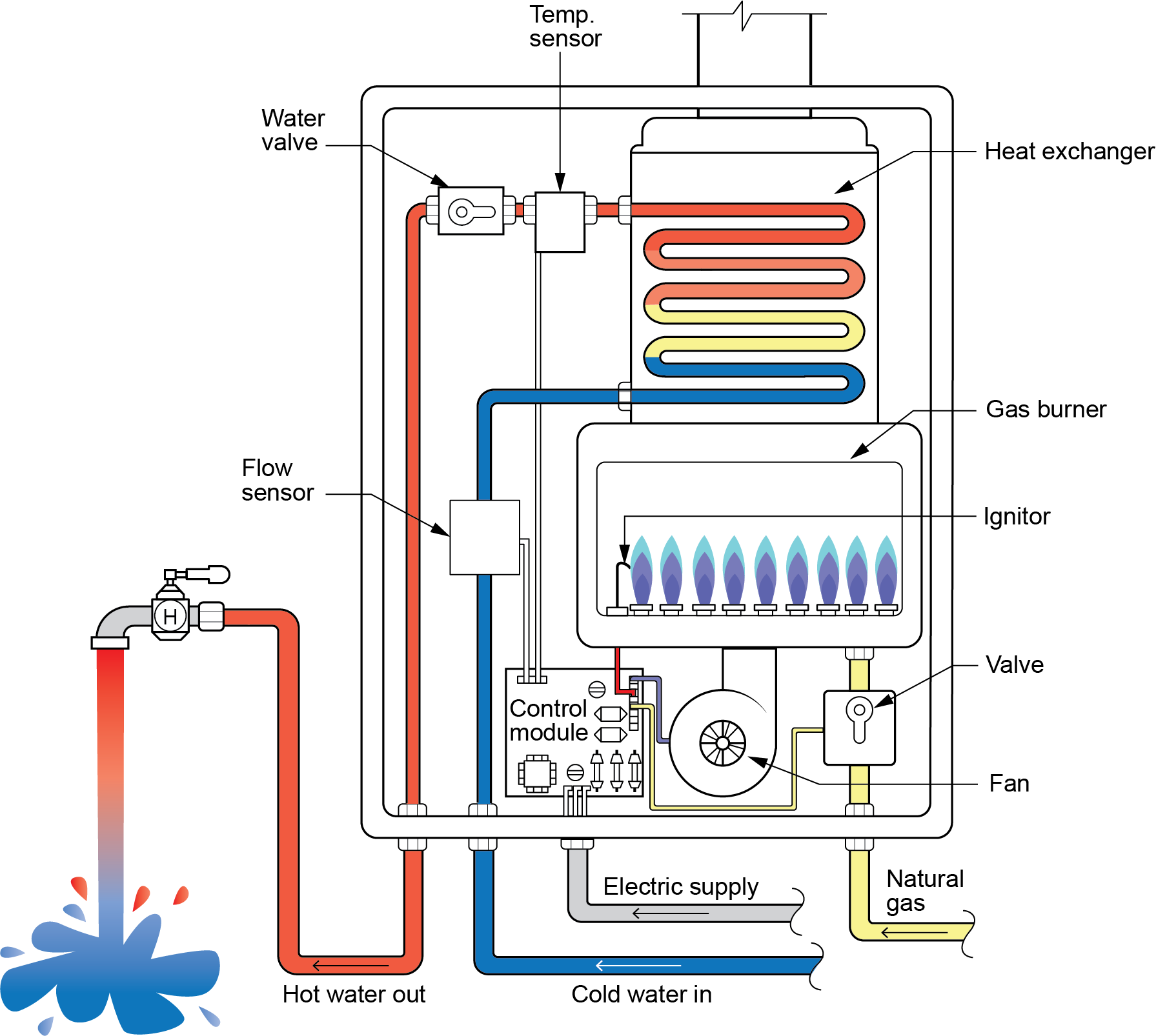
The basic operation of the on-demand system shown in Figure 18 is as follows:
- A hot water faucet is opened.
- Cold water enters the heater through the flow sensor, alerting the control module that hot water is needed.
- The control module turns on the fan, opens the gas valve, and ignites the burner.
- The water is drawn through the heat exchanger and heated by the gas burner.
- The temperature sensor alerts the control module as the water temperature begins to rise.
- The control module may reduce the gas valve’s flow rate, which modulates the burner flame as the desired water temperature is reached.
- When the hot water faucet is closed, the flow sensor signals the control valve to turn off the unit.
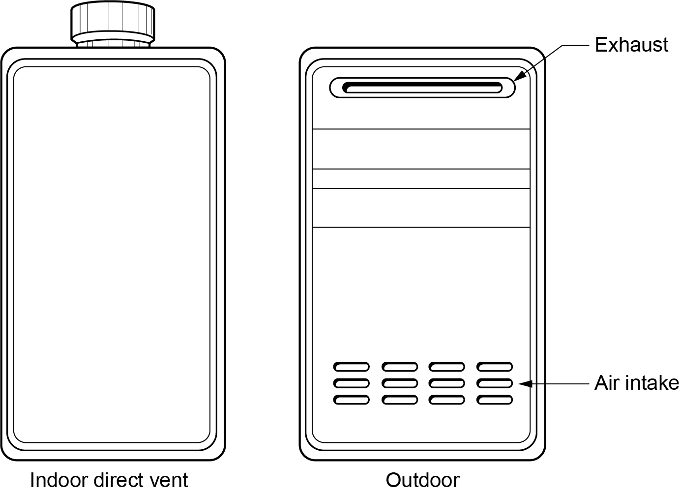
Tankless water heaters are typically available as condensing indoor direct vent units, as well as outdoor units (Figure 24). Outdoor units are unvented because they receive their combustion air from the environment around them and expel the exhaust the same way.
Plumbers often install a hot water recirculation system to ensure immediate hot water at distant fixtures. The low recirculation flow rate and very low heat demand that occur during recirculation are difficult for a standard on-demand water heater to accommodate. If a recirculation system is used with a tankless water heater, the water heater must be approved for recirculation. The approved models, sometimes referred to as hybrids, use a small storage tank (buffer tank) immediately after the heat exchanger (Figure 25). By using a circulating pump with the buffer tank, water can be circulated through the buffer tank and system without operating the tankless heater until the water temperature leaving the buffer tank drops below the setpoint. Water is then diverted through the tankless heater for reheat.
Furnaces
Many houses and small commercial buildings use a central forced air system for space heating. This section focuses on the heart of the system, the furnace, which includes a blower that circulates the air through a heat exchanger through ductwork to the rooms. Forced air heating systems will be discussed in greater detail in B-1.3 Residential Forced Air Heating Systems.
Although the minimum efficiency for residential furnaces sold in Canada is now 90%, a gasfitter can still be expected to work on older, lower-efficiency models. Some common terms used to classify furnaces by their efficiency are:
- Conventional furnace, standard-efficiency, or low-efficiency: below 78% efficient
- Medium or mid-efficiency (sometimes called standard-efficiency): 78% to 89% efficient
- High-efficiency or condensing: 90% efficient and above
- Energy Star: 95% efficient and above
A modern high-efficiency furnace could work as a standalone heat source or could be used as a companion to other heating, ventilation, air conditioning, and refrigeration (HVACR) equipment. For example, a furnace can be a single-stage, two-stage, or multi-stage (modulating) model and can be combined with a heat pump, solar system, air conditioning, or any other alternate heating or cooling source. This can be challenging for installers and service technicians, so a strong understanding of all the components and installation requirements is necessary.
A condensing furnace uses two heat exchangers, a primary and secondary. The secondary heat exchanger is much more restrictive to the flue gas, allowing more heat energy to be removed to the point that condensing occurs (Figure 26).
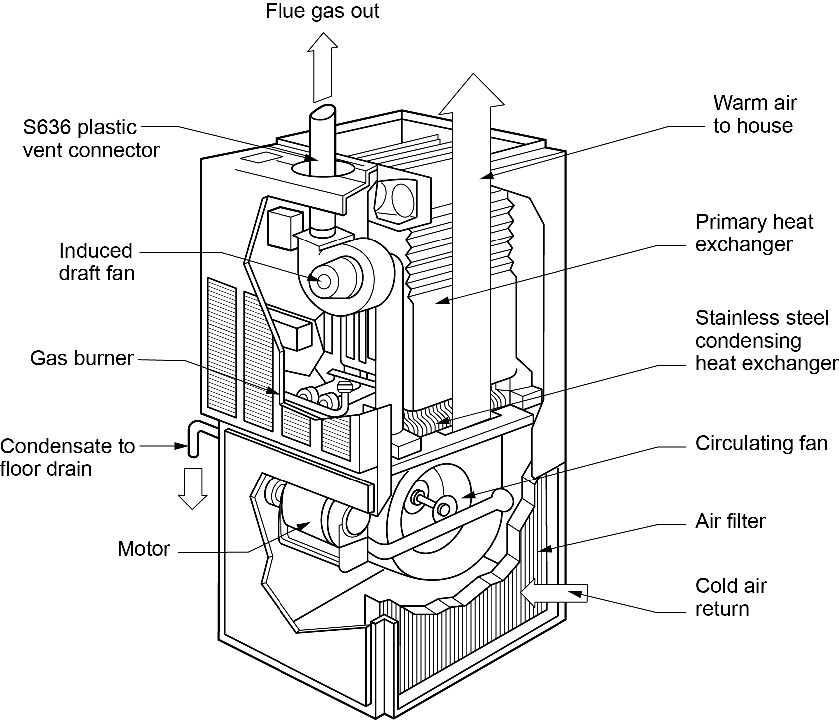
Because of the restrictive nature of the secondary heat exchanger and the loss of heat energy from the flue gas, the appliance cannot vent naturally. The inducer fan must be able to draw the flue gas from the secondary heat exchanger and create sufficient pressure to force it through the venting system to the outdoors.
Since the venting system operates with a positive vent pressure and lower flue gas temperatures, a plastic sealed vent is typically used.
Hot Water Boilers
Domestic and commercial space heating is commonly done with hydronic heating systems. The information here is a very brief introduction to gas hot water boilers, which are one of the more common hydronic heating energy sources. Hydronic heating systems will be discussed in greater detail in B-2 – Hydronic Heating and Cooling Generating Equipment.
A hot water boiler is completely filled with water, and the combustion control system is used to maintain a preset operating temperature in the boiler water space. Hot water produced by a boiler is pumped through piping and delivered to heat-emitting equipment throughout the building. Once the heat has been extracted, the water is returned to the boiler through heating return mains, and the cycle begins again.
Boilers can be classified in many ways, such as by the fuel they use, heat output rating, construction material, heat exchanger geometry, and methods for exhausting combustion gases. However, from the standpoint of hydronic heating system design, it is important to distinguish between conventional “non-condensing” boilers and condensing boilers. Conventional boilers (Figure 27, left) are intended to operate so that the water vapour produced during combustion does not condense on a sustained basis within the boiler combustion chamber. Nearly all boilers with cast iron, carbon steel, or copper heat exchangers fall into this category.
The inlet water temperature at which condensation begins to form on the boiler’s heat exchanger is approximately 54°C (130ºF). This temperature is known as dewpoint. The lower the entering water temperature, the more condensate that forms. Therefore, it is imperative that conventional boilers are operated with inlet water temperatures above 60°C (140°F) so that sustained flue gas condensation does not occur within the boiler.
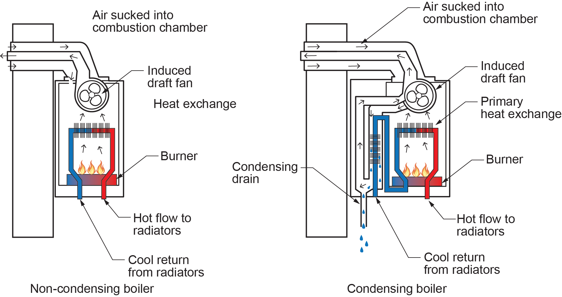
Condensing boilers are constructed with more heat exchanger surfaces made of stainless steel or aluminum. These heat exchangers are capable of extracting more heat from the exhaust gases compared to the heat exchangers used in conventional boilers. When operated with suitably lower inlet water temperatures, these boilers can easily cool the exhaust stream below the dewpoint temperature of the water vapour, thus causing condensation to occur (Figure 27, right). The lower the entering water temperature, the greater condensing and efficiency it will achieve.
Nearly all condensing boilers can vary their heat output from a maximum rate down to approximately 20% of that maximum output. These boilers are said to be modulating and often referred to as “mod/con” boilers (Figure 28).
Condensing boilers can provide significant energy savings due to operating efficiencies, from as high as 98%, compared to a peak efficiency of 87% for a conventional boiler. However, installing a condensing boiler does not guarantee achieving anticipated savings. A condensing boiler is not a compact LED light bulb; an installer cannot simply plug it into a typical system and expect it to save energy. Careful attention must be paid to the heating water system as a whole.
Designing an energy-efficient heating system using condensing boilers is completely different than designing a conventional boiler system, where the goal is to keep the boiler return water temperature above 60°C (140°F). This difference requires significant variations in systems, including distribution piping design, operating system temperatures, heat emitter selection, boiler sequencing, and system control.
If an existing system cannot be redesigned to return water near or well below 54°C (130°F) for a good portion of the heating season, consider a non-condensing boiler, which can operate with an efficiency of up to 87% with a return water temperature of 60°C (140°F). Depending on market demand and efficiency regulations in the area, however, a non-condensing boiler may not be available. In this case, system design modifications will be required in addition to the boiler replacement.
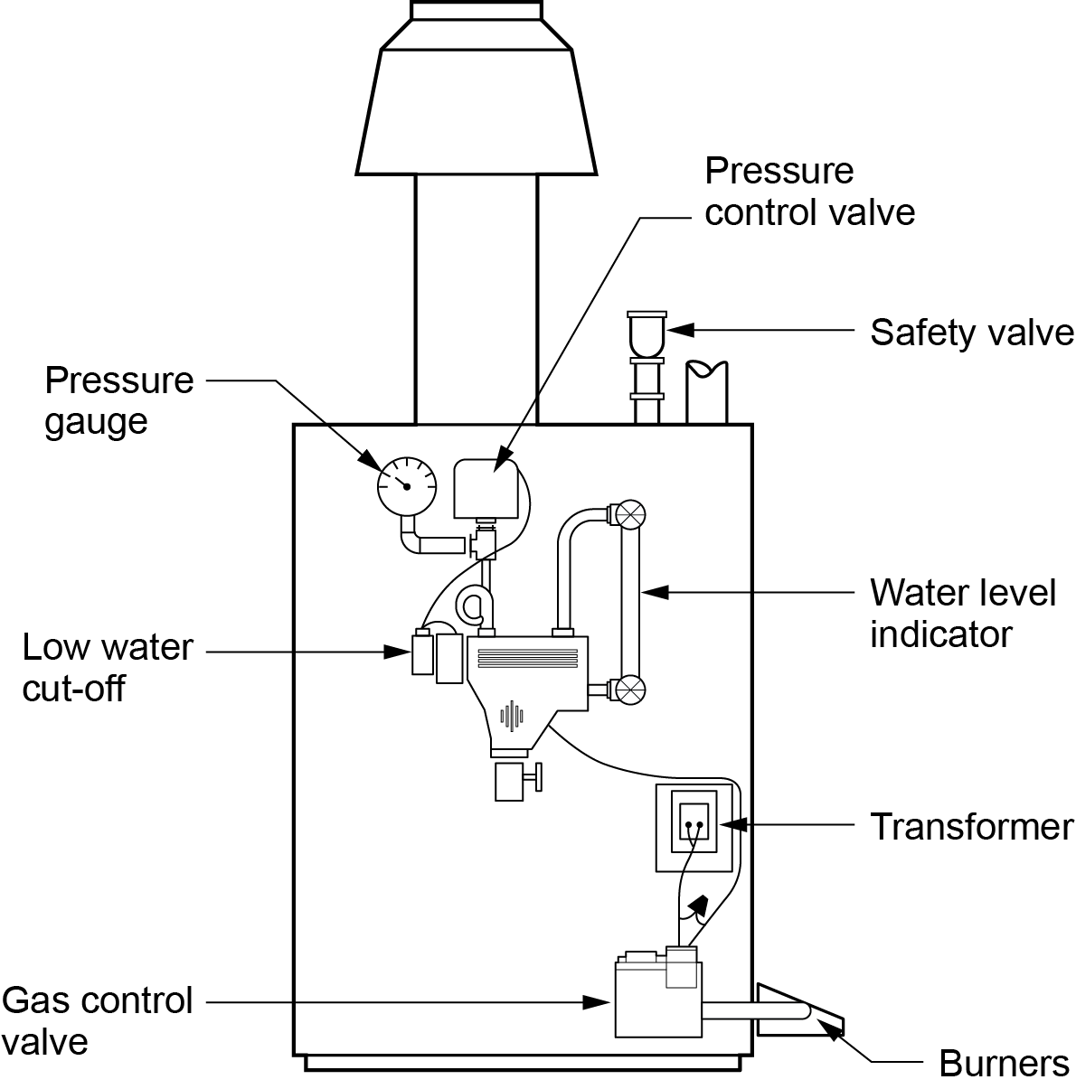
Steam Boilers
Steam heating is not commonly used for domestic purposes. Steam boilers (Figure 29) are used to heat large spaces or used in industrial processing. A steam boiler is partially filled with water, and a space at the top of the boiler allows steam to accumulate. The combustion safety control system monitors the pressure in the steam space. As steam is drawn from the boiler, the pressure drops and the boiler fires to generate more steam.
The pressurized steam can flow from the boiler through piping, unaided by an external energy source, such as a pump. Once the steam utilization equipment takes advantage of the latent heat in the system, steam traps allow the condensate to enter the condensate return main. The condensate is collected in a tank and returned to the boiler by a pump, as required, to maintain the boiler water level.
 Self-Test A-1.2: Types of Gas Fired Appliances
Complete Self-Test A-1.2 and check your answers.
If you are using a printed copy, please find Self-Test A-1.2 and Answer Key at the end of this section. If you prefer, you can scan the QR code with your digital device to go directly to the interactive Self-Test.

References
30-inch wide gas range with true convection…. Model: MGR8800FZ. (n.d.). Maytag Canada. https://www.maytag.ca/en_ca/kitchen/cooking/ranges/single-oven-freestanding/p.MGR8800FZ.html
Bango, M. (n.d.). Patio Outdoor Free Stock CC0 Photo [digital image]. StockSnap.io. https://stocksnap.io/photo/patio-outdoor-ISWZOYDFU7
Chew, J. (2017, September 11). Direct-vent, vent-free, B-vent gas fireplaces—What’s the difference? The Fireside Group. https://www.thefiresidegroup.com/post/2017/12/10/direct-vent-vent-free-b-vent-gas-fireplaces-whats-the-difference
Direct vent wall furnace installation and operation manual. (2018). Rinnai Corporation. https://media.rinnai.us/salsify_asset/s-b533839e-3f7d-437e-93c8-225bb4cd77b2/200000072-EX08CT,%20EX11CT%20(202FTA,%20265FTA)%20Installation%20and%20Operation%20Manual.pdf
Family Handyman. (2023). Common dryer repairs you can do yourself. Home Service Publications, Inc. https://www.familyhandyman.com/article/common-dryer-repairs-you-can-do-yourself/
Modern Fireplace Ideas. (n.d.). Direct vent FAQ. Modern Fireplace Ideas. https://modernfireplaceideas.com/direct-vent-faq/
ServiceWhale. (2021). What is power vent water heater? ServiceWhale. https://servicewhale.com/pages/what-is-power-vent-water-heater
Skilled Trades BC. (2021). Book 1: Fuel gas systems, Heating and cooling systems. Plumber apprenticeship program level 2 book 1 Harmonized. Crown Publications: King’s Printer for British Columbia.
Trades Training BC. (2021). A-1: Introduction to gas-fired appliances. In: Plumber Apprenticeship Program: Level 2. Industry Training Authority, BC.
Media Attributions
All figures are used with permission from Skilled Trades BC (2021) unless otherwise noted.
- Figure 1 Domestic gas range (Model: MGR8800FZ) is from Maytag Canada (n.d.) and is used with permission for educational purposes only.
- Figure 2 Commercial cooking equipment (adapted) is from pxhere and is used under a CC0 1.0 Universal public domain license.
- Figure 4 Image originally adapted from Model UGP-9RV-SSO-C-REV-E by Unique Off Grid (n.d.) under Fair Dealing Guidelines for educational purposes.
- Figure 5 Image originally adapted from Dryer Repairs You Can Do Yourself | Family Handyman by Trades Training BC (2021) under Fair Dealing Guidelines for educational purposes.
- Figure 6 Diagram originally adapted from 200000072-EX08CT, EX11CT (202FTA, 265FTA) Installation and Operation Manual.pdf (Rinnai US, 2018) under Fair Dealing Guidelines for educational purposes.
- Figure 8 Suspend gas fired unit heater by Rod Lidstone, is used under a CC BY 4.0 license.
- Figure 12 Tube heaters with emitter guards, by Rod Lidstone, is used under a CC BY 4.0 license.
- Figures 14, 15 and 18 are adapted from Direct-Vent, Vent-Free, B-Vent Gas Fireplaces—Whats the Difference? (Chew, 2017), and are used with permission.
- Figure 16 Co-linear chimney venting is adapted from Modern Fireplace Ideas (n.d.), and is used with permission.
- Figure 17 Direct vent vs power vent (left side – adapted) from “What is power vent water heater?” by ServiceWhale, (2021), is used with permission.
- Figure 20 Gas firepit, by Matt Bango via StockSnap is used under a CC0 license.
- Figure 27 Boiler types was originally adapted from Gas Boiler Diagram: the Basics Everyone Should Know | Gas Boilers (gasboilerguide.com) by Trades Training BC (2021).
- Figure 28 Wall-mounted Mod/Con Boiler, by Rod Lidstone, is used under a CC BY 4.0 license.
A gas-fired refrigerator that uses heat from a gas flame to drive a chemical process involving ammonia, water, and hydrogen to produce cooling—without a compressor. (Section A-1.2)
A sealed combustion gas appliance that draws air from outside for combustion and vents exhaust gases directly outside, improving safety and efficiency. (Section A-1.2)
A safety device that detects dangerous levels of carbon monoxide gas and may activate a shut-off mechanism on gas appliances. (Section A-1.2)
A component used in some gas appliances to shut off the gas supply in case of sensor failure or unsafe operating conditions, often used with CO detectors. (Section A-1.2)
(Metal-Oxide-Semiconductor Field-Effect Transistor); A small electronic part that helps turn gas appliances on or off safely. It controls how electricity flows to important safety parts like sensors or shut-off devices. (Section A-1.2)
The ductwork used in gas dryers to vent humid air and combustion by-products to the outdoors, as required by code. (Section A-1.2)
A specialized oval-shaped vent system designed for use with natural draft appliances like recessed wall furnaces, allowing installation within wall cavities. (Section A-1.2)
A self-contained, fan-forced, vented gas heater typically suspended from ceilings in garages or industrial spaces for localized space heating. (Section A-1.2)
A non-vented heating appliance that uses a porous burner surface to radiate high levels of heat, often used in large open areas like warehouses or patios. (Section A-1.2)
A gas fireplace that can be safely installed close to combustible materials because it is heavily insulated. It is designed for new construction or renovations where no existing fireplace is present. (Section A-1.2)
A safety design feature in gas water heaters that prevents the ignition of flammable vapours outside the combustion chamber. Especially important in areas like garages where flammable liquids may be stored. (Section A-1.2)
The intentional introduction of outdoor air into a space to control indoor air quality by diluting and displacing indoor pollutants; can also be used for purposes of thermal comfort or dehumidification. (Section A-1.2; Section A-3.4)
