A-1.1 Characteristics of Gas Appliances
Installing and commissioning gas appliances requires a thorough knowledge of the most common characteristics that will affect the installation and operating environment of the gas appliance.
All of the characteristics identified in this chapter are covered in much greater detail in future studies. The primary objective at this level of study is to make installers aware of the significance of these characteristics. This means they should find more information about each specific appliance when performing installation, operation, or maintenance.
Appliance Design
The gas appliance design can include many characteristics. Some of these are more internal to the appliance and will predominately be component-related and impact the operation and maintenance of the appliance. Other characteristics are more external to the appliance and therefore may have a greater effect on the environment and installation.
Internal (Component) Characteristics
Internal characteristics will include types of burners, ignition systems, controls, and safeties.
Burners
Burners are designed in many shapes and sizes to accommodate the wide variety of heat exchangers and combustion chamber requirements. The type of burner an appliance contains will have an effect on the installation and service requirements of the appliance. The two primary categories of burners, non-mechanical and mechanical, are distinguished by how the combustion air is supplied.
Non-mechanical or “atmospheric burners” rely on natural draft to supply the required combustion air. Because atmospheric burners have lower efficiency and are more susceptible to flue gas spillage, they are becoming less common in contained combustion chamber appliances.
High-efficiency appliances contain mechanical burners, which use a fan or blower to deliver the combustion air and can therefore achieve a more controlled gas/air mixture and higher efficiency.
Pilots and Ignition Systems
A pilot is a flame that ignites a main burner or burners. Most pilot burners are controlled by a safety device that shuts off the gas supply to the main burner(s) if the pilot flame is extinguished. There are different types of pilot burners. Some will remain lit continuously while others will only be lit on a call for main burner ignition. It is important for the installer to be familiar with the type of pilot that each appliance contains, as there will be specific start-up requirements for each.
Many appliances today do not use a pilot burner to ignite the main burner. The main burner is ignited directly by a spark or hot surface igniter. These will also have specific service and troubleshooting procedures that the installer will need to be familiar with.
Controls and Safeties
The control system of an appliance must initiate a safe light-up, supervise the run period, and provide a safe shutdown of the appliance. Should overheating, overpressure, or flame failure occur, the control system must be able to safely shutdown the appliance. If any part of the control system is improperly installed or improperly wired, a safe shutdown may not occur, which could lead to a potentially dangerous situation.
The appliance controls will be individual components of distinct circuits with specific functions. For example, among other components, the combustion safety circuit could include a thermocouple and safety shut-off valve. The main burner control circuit could, on the other hand, include a thermostat, high temperature limit, and main gas valve. The ability to interpret the appliance wiring diagram(s) is an essential skill for identifying each control component and its function.
The individual control components within each circuit relies upon a variety of physical characteristics for their operation. For example, expansion of solids and liquids, electromagnetism, the thermoelectric effect, and electricity are all used in varying capacities. A person troubleshooting gas appliances will require a good knowledge of these concepts
Gas Appliance External Characteristics
The external characteristics, such as the venting or the heat exchange process, require consideration of such things as:
- Location (indoor, outdoor, type of living space)
- Clearances from combustibles to the appliance and vent
- Type of venting materials to be used
- Method of air supply
Vented or Non-Vented
Vented gas appliances typically have an enclosed combustion chamber and vent the combustion products to the outside atmosphere. Non-vented gas appliances, as the name implies, do not have a vent. Therefore, all of the combustion gases are released directly into the immediate surroundings.
Indoor non-vented gas appliances are primarily used for cooking equipment. Emissions from these appliances can contribute to poor air quality, if the appliances are used for extended periods without a venting hood. Commercial kitchens will be equipped with large exhaust systems to ensure adequate air change. Unvented gas space-heating appliances are not permitted for use in indoor applications.
Venting and Air Supply Characteristics
Non-vented appliances such as ranges will have an open flame. Therefore, all of the air for combustion is immediately available from the surrounding air. On the other hand, the combustion air supply for a vented appliance will be drawn in through intake openings in the combustion chamber or forced combustion fan.
There are two common methods of air supply for vented gas appliances:
- Direct vent systems
- Room air systems (non-direct vent)
The size, location, installation methods, and type of material employed in venting systems are largely determined by the manufacturers of the appliance and vent system. Each method is appliance specific and will require different installation considerations. These are detailed in the manufactures installation instructions and Clause 8 of the CSA B149.1 Gas Installation Code.
Direct Vent
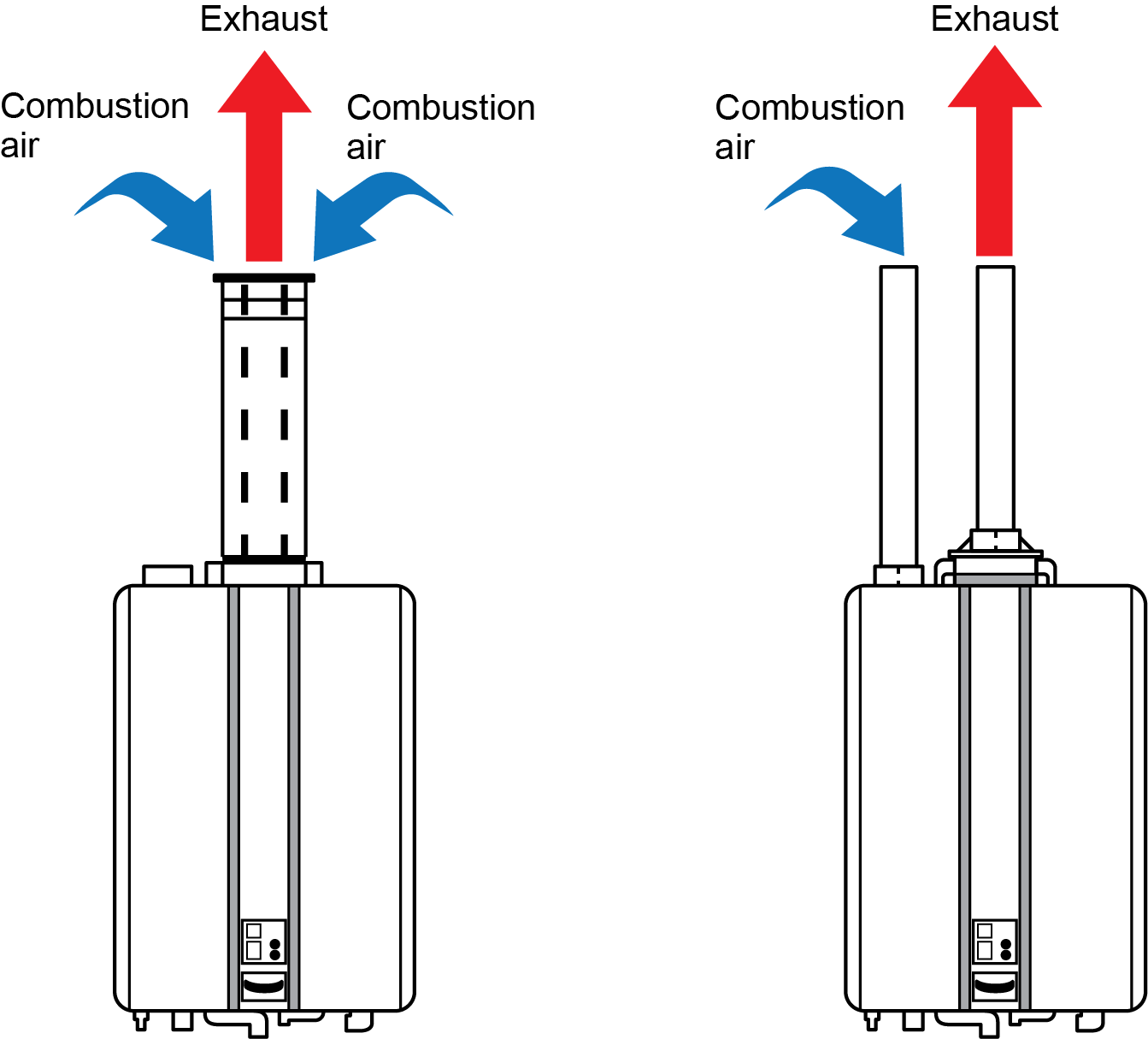
Direct vent systems have a sealed combustion chamber where all of the air for the appliance is taken directly from the outside, and the flue gas is discharged directly to the outdoors. Direct vent systems typically have two piping options; concentric coaxial pipe or twin pipe.
For coaxial vents, the combustion air and exhaust flow directly through a single connection to the appliance. Hot exhaust exits through the interior tube, while combustion air enters through the outer layer (Figure 1, left).
For twin pipe systems, the combustion air and exhaust flow directly through separate pipes and penetrations (Figure 1, right).
There are many termination options available for direct vent systems, including adapters that enable the installer to convert a two-pipe system to a concentric termination. Because manufacturers of venting materials make fittings for many brands of appliances, appliance manufacturers must list which given brand of venting is acceptable for use on a specific appliance.
Room Air System
Non–direct vent gas appliances draw all of their air supply requirements from the internal room air, which requires an outdoor air supply dedicated to the gas appliance. For gas appliances dependent on room air, outside air is normally brought to the proximity of the gas appliance via a duct. This is referred to as passive air supply, in contrast to a mechanical air supply such as a fan. If a mechanical air supply is used, it must be properly sized and interlocked with the appliances to shut-off the gas in the event of an air supply failure.
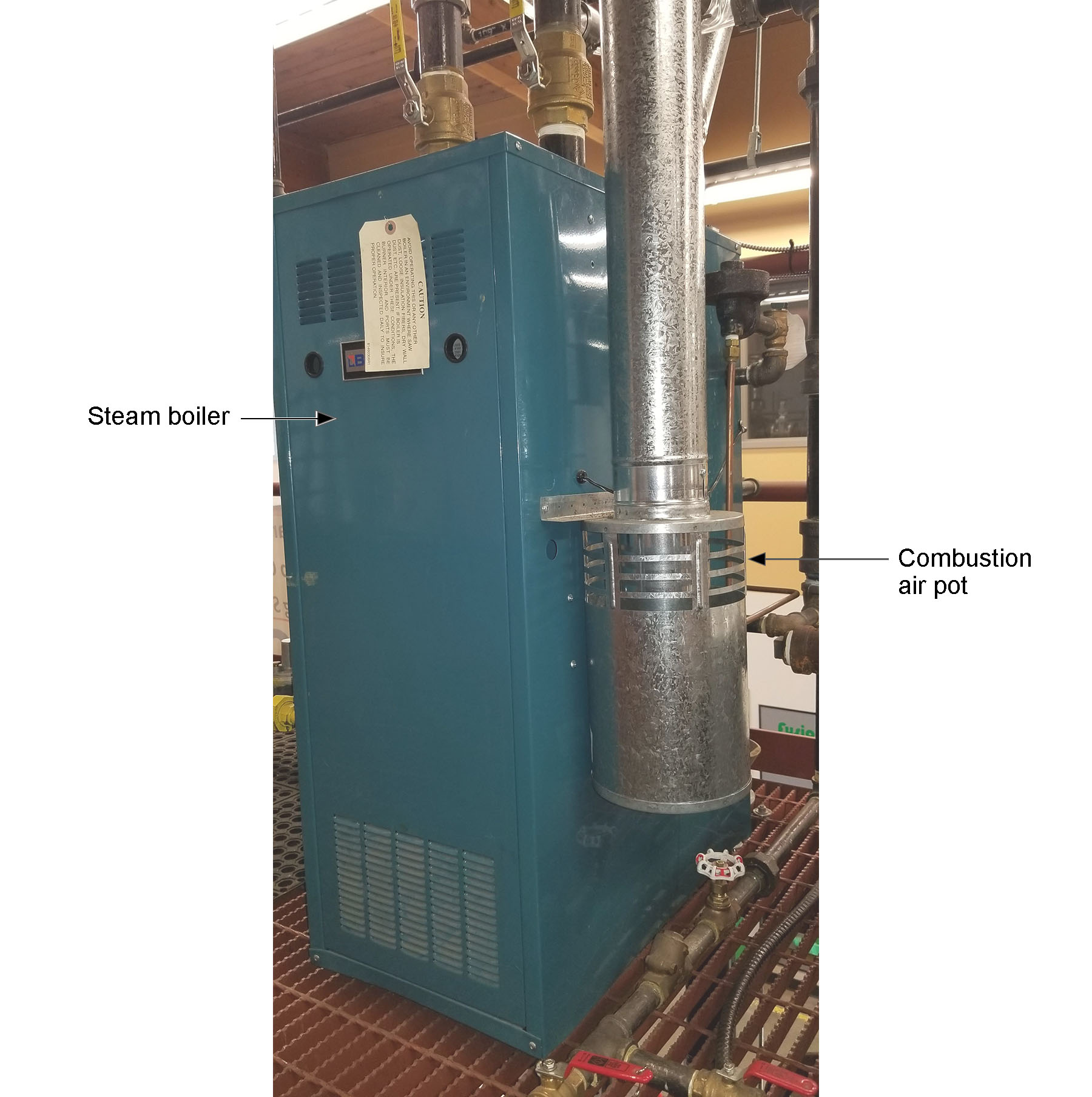
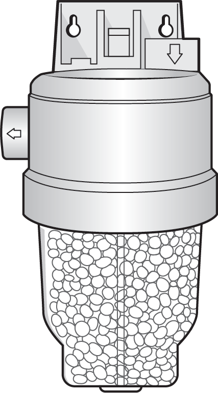
Some jurisdictions encourage the use of a thermal trap (combustion air pot, Figure 2) at the termination of the passive air supply duct to inhibit the flow of heated air out of the duct when the combustion equipment is not firing (Figure 2).
With such a large selection of the venting options to choose from, the manufactures’ vent installation instructions have become more detailed than the general installation instructions, to the point that they are often a separate installation document.
Heat Exchange Characteristics
The purpose of gas appliances is to transfer heat energy by way of conduction, convection, radiation, or a combination of these.
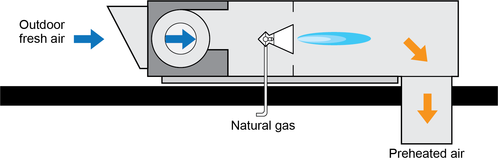
One type of heat exchange is called direct fired, in which the burner is fired directly into the process air stream to heat it. An example is a direct fired make-up air (DFMA) unit, which is used in commercial and industrial applications to preheat the ventilation air. Figure 3 illustrates a common rooftop-type unit. Direct fired heaters have an exposed flame similar to a stove top or grill, in which the combustion products are added to the heated air. Because of this, direct fired heaters are not used for places where people may sleep (hotels, homes, clinics, etc.).
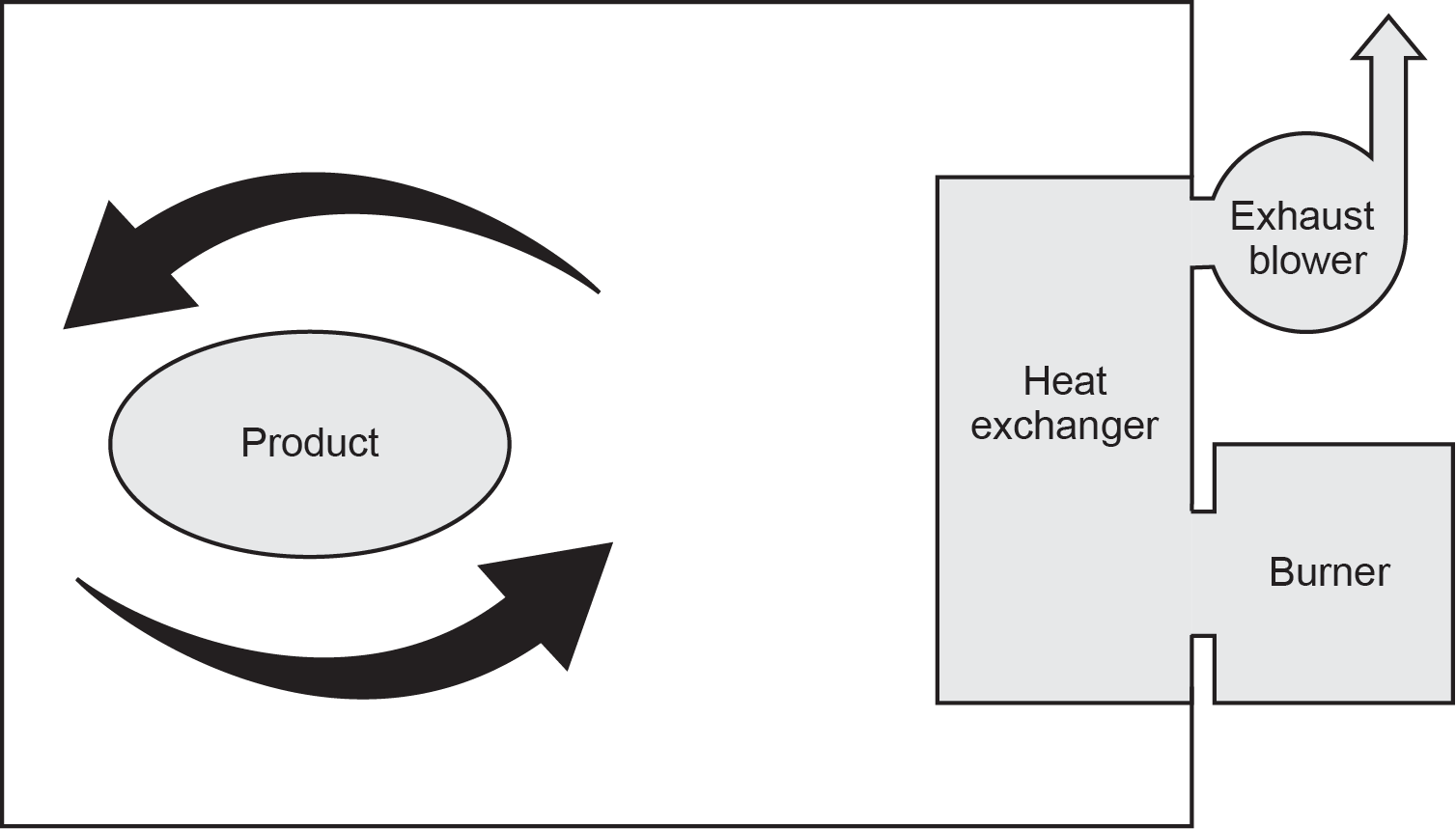
In an indirect fired heater, the burner is fired into a heat exchanger. The product (air or water) is heated by passing over the heat exchanger, allowing the combustion byproducts to remain within the heat exchanger, which is then exhausted through a flue (Figure 4). Furnaces and boilers are both examples of indirect fire gas appliances.
Efficiency
Because direct fired appliances convert nearly all of the combustion gasses used into hot air, they are considered to be 100% combustion efficient, although approximately 8% of that energy is used for water vapour formation during combustion.
The efficiency of indirect fired gas appliances is determined by the appliance’s ability to extract heat from the flue products. Efficiency factors include the type of heat exchanger materials, number of internal passes of the flue gas, and temperature of the process fluid (air or water) on the other side of the heat exchanger walls.
If the gas appliance extracts enough heat energy, condensing of the water vapour in the flue gas occurs. For every pound of water condensed from the flue gas, the heat exchanger gains approximately 970 BTUs of heat energy, referred to as “latent heat.”
The latent heat increases the efficiency levels well into the 90% range but also presents new problems. The condensate has been exposed to CO2 in the flue gases, which creates carbonic acid. Therefore, the heat exchanger has to be constructed of a material that can be exposed to condensate — usually a stainless-steel alloy. Many jurisdictions now require acid neutralizers (Figure 5) to be installed to raise the pH level prior to discharging the condensate to the building’s drainage system.
Characteristics Summary
Each appliance is designed for a specific application, giving it unique characteristics. We can see that these characteristics will affect the installation, operation or maintenance of the appliance. It is therefore critical that gasfitters make themselves familiar with the specific documents and regulations relative to each appliance they are working on.
 Self-Test A-1.1: Characteristics of Gas Appliances
Complete Self-Test A-1.1 and check your answers.
If you are using a printed copy, please find Self-Test A-1.1 and Answer Key at the end of this section. If you prefer, you can scan the QR code with your digital device to go directly to the interactive Self-Test.

References
Skilled Trades BC. (2021). Book 1: Fuel gas systems, Heating and cooling systems. Plumber apprenticeship program level 2 book 1 Harmonized. Crown Publications: King’s Printer for British Columbia.
Trades Training BC. (2021). A-1: Introduction to gas-fired appliances. In: Plumber Apprenticeship Program: Level 2. Industry Training Authority, BC.
Media Attributions
All figures are used with permission from Skilled Trades BC (2021) unless otherwise noted.
- Figure 2 Combustion air pot on a steam boiler by Rod Lidstone, is used under a CC BY license.
A type of pipe made of two pipes, one inside the other. The outer pipe carries air, while the inner pipe carries the fuel or exhaust, helping to safely vent gases while bringing in fresh air for combustion. (Section A-1.1)
A thermal trap prevents cold air from entering the system while allowing hot air to escape, helping maintain the right temperature for combustion air and ensuring safe fuel burning. (Figure 2, Section A-1.1)
