A-4.3 Electrical Testing Instruments
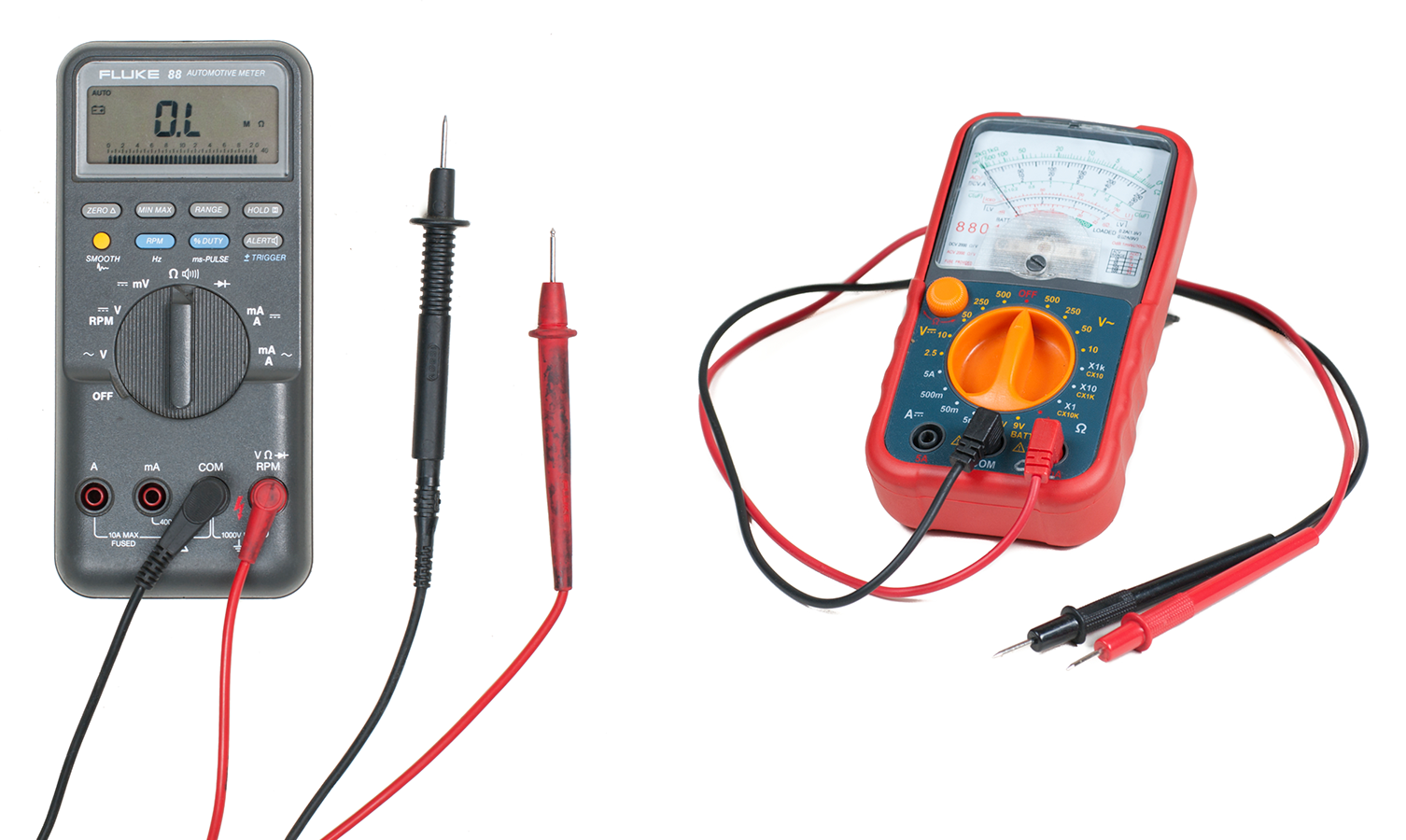
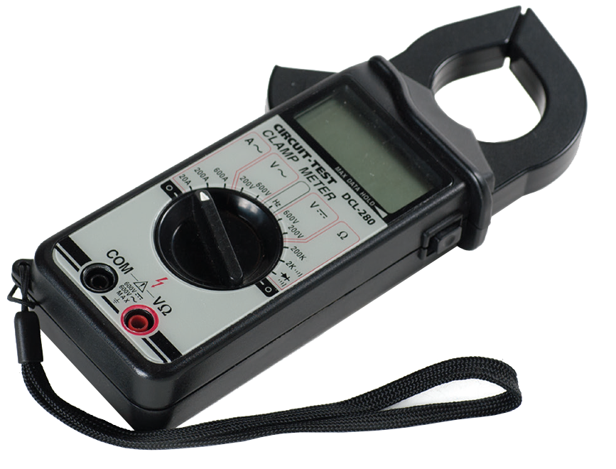
Electrical measuring and test instruments include various types of meters, recorders, and analyzers. These instruments may be analogue or digital types of units (Figure 1).
Analogue instruments indicate measured values with a scale and pointer display. The pointer’s movement is directly and continuously related to the measured quantity.
Digital instruments interpret the measured quantity electronically in discrete numerical data (digits). They have a numerical display formed by light-emitting diodes (LEDs) or liquid crystal displays (LCDs). Reading a digital meter involves little or no interpretation, and digital meters can often read current in the range of microamps. Therefore, the digital multimeter (DMM) is the most common type in use today.
Describe Electrical Meters
A digital multimeter (DMM) combines the features of a voltmeter, ammeter, and ohmmeter. Digital multimeters also have advanced features that vary among models and manufacturers.
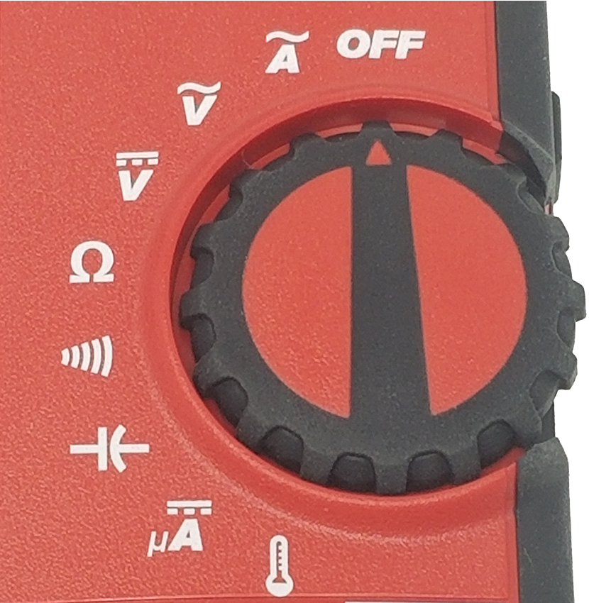
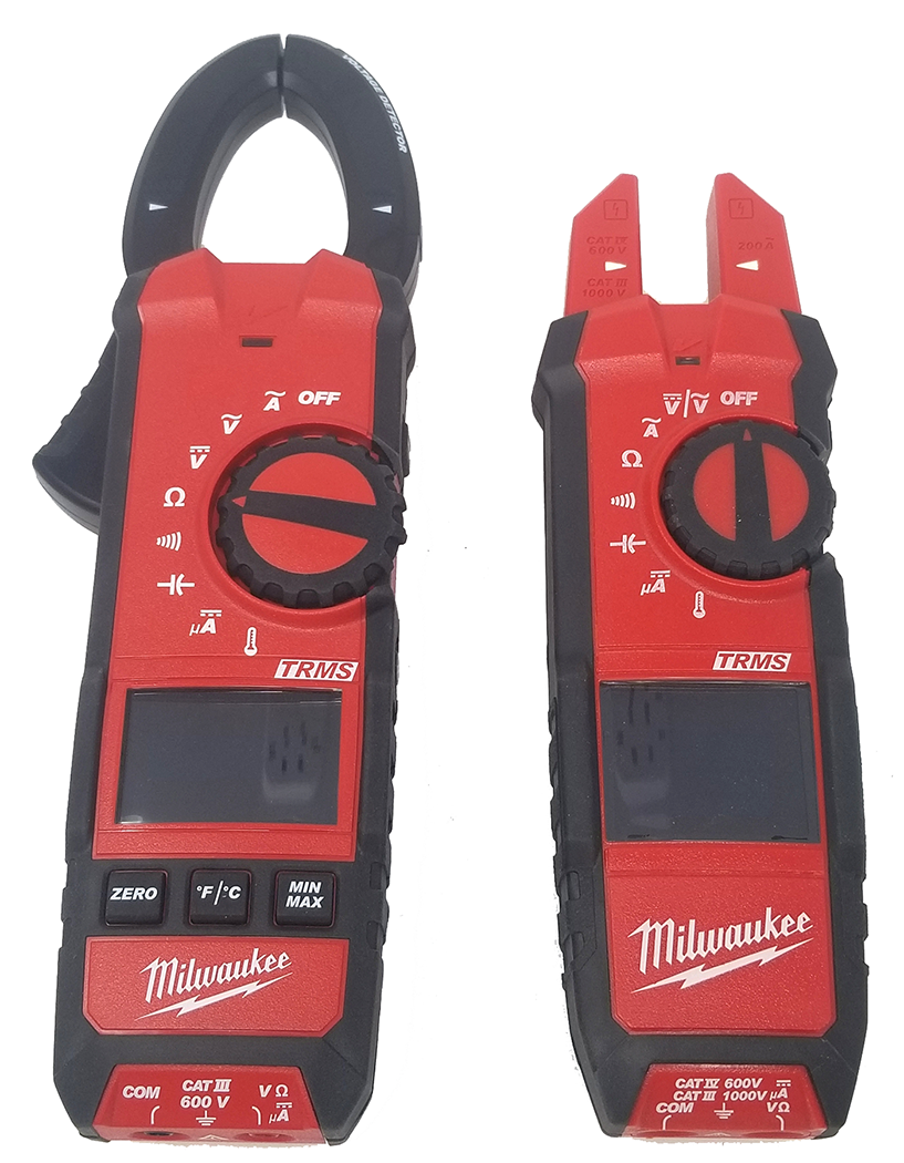
The DMM has a function control switch to select the electrical quantity to be measured (Figure 2). Some DMMs require manual setting of ranges, although most have an autoranging feature that automatically selects the range with the best accuracy and resolution for the measurement. When the meter leads are connected to the device to be tested, the meter automatically selects the proper range and displays the values.
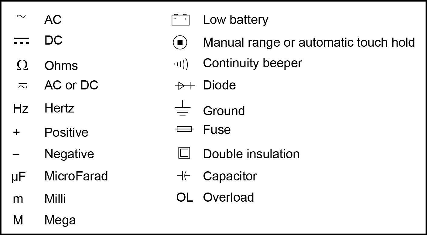
Many meters use symbols on the display, switch, and connections. Figure 3 shows some common symbols used.
Voltmeter Functions
Voltage is the electrical force that drives current through an electrical circuit. Voltage drop is defined as the potential difference between two points in an electrical circuit. There are two types of voltage sources: AC voltage and DC voltage. The current flow caused by an AC voltage source changes in both magnitude and direction at regular intervals. The current flow caused by a DC voltage source does not change direction. Voltage measurements are taken using the DMM voltmeter functions.
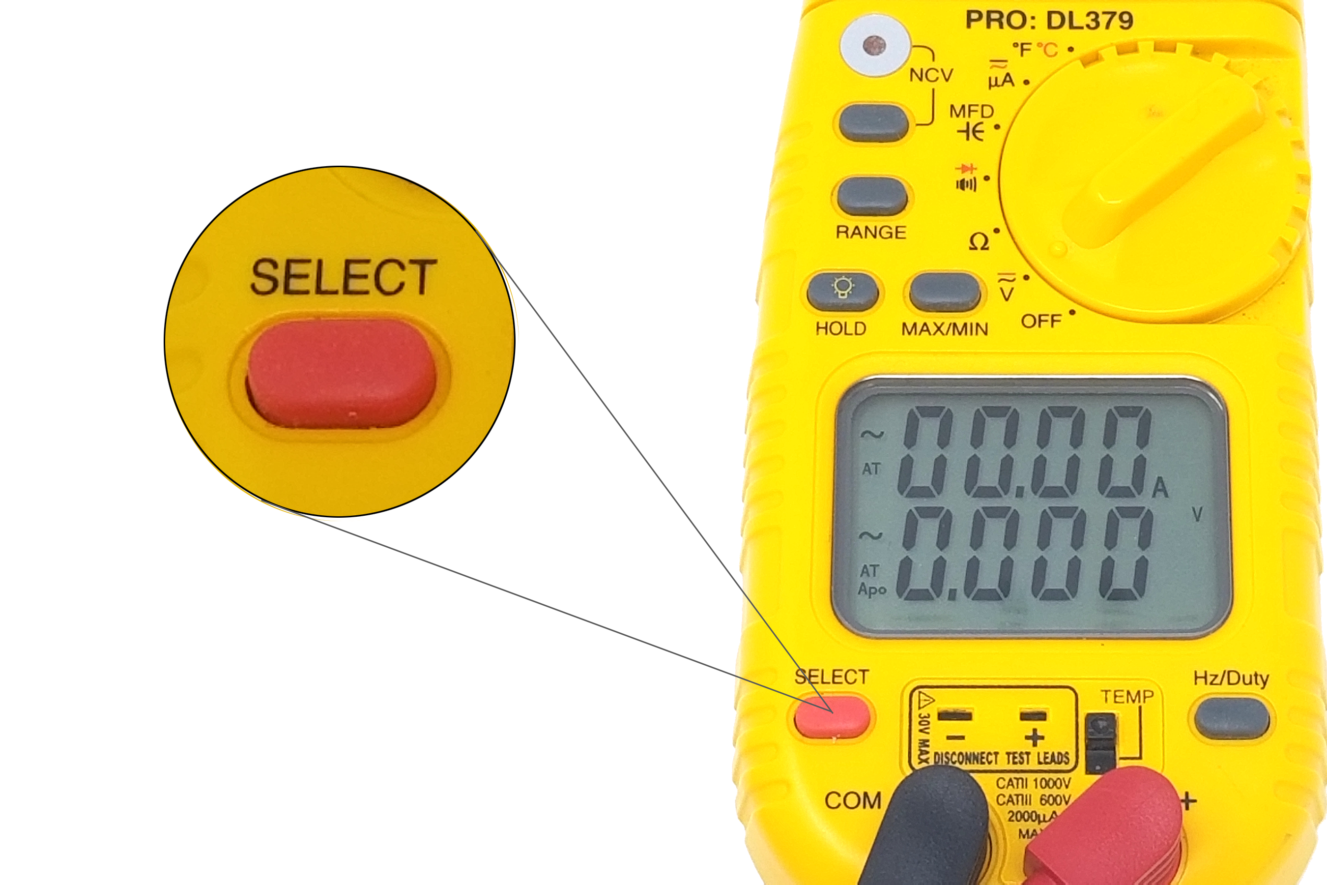
The AC (~) voltage function is commonly used to test and troubleshoot receptacles, gas appliance power supply, transformers, and other AC control circuits. A DMM set for the DC (~) voltage function can be used to test battery banks and gas pilot thermocouples and troubleshoot DC motors, DC generators, and other DC circuits. Some meters have function switches with multiple options at some selections. These may require that the operator push an additional select button to choose the alternate unit.
Ammeter Function
The ammeter function is used to measure current in an electrical circuit. Current flows through a circuit when a power source is connected to a device or load. Current is the flow of electrons in a circuit when voltage is applied to the circuit. This current flow is inversely proportional to the resistance of the load. Current is measured in amperes (A), milliamperes (mA), or microamperes (µA). The word “ampere” is commonly shortened to “amp.” Current measurements are taken to ensure that the electrical circuit or components are not overloaded.
Using a DMM to measure current (amperage) requires connecting the meter in series with the circuit being tested. This involves disconnecting a wire from a terminal and connecting the test leads between the wire end and the terminal it was removed from.
This means that the meter is now part of the circuit, and the amperage that flows through the circuit will also flow through the meter. This creates a problem in that the meter leads must be heavy enough to allow current flow, which causes heat, without burning up. Therefore, most multimeters do not have the ability to measure any AC or DC amperage above the milliamp range when using test leads to reduce risk of overloading. There are DMMs available with clamp-on current probe accessories to measure higher current values and safely take current readings without opening a circuit (Figure 5). The most common clamp-on accessories are available for AC currents only, but there are also types for both AC and DC currents.
Ohmmeter Function
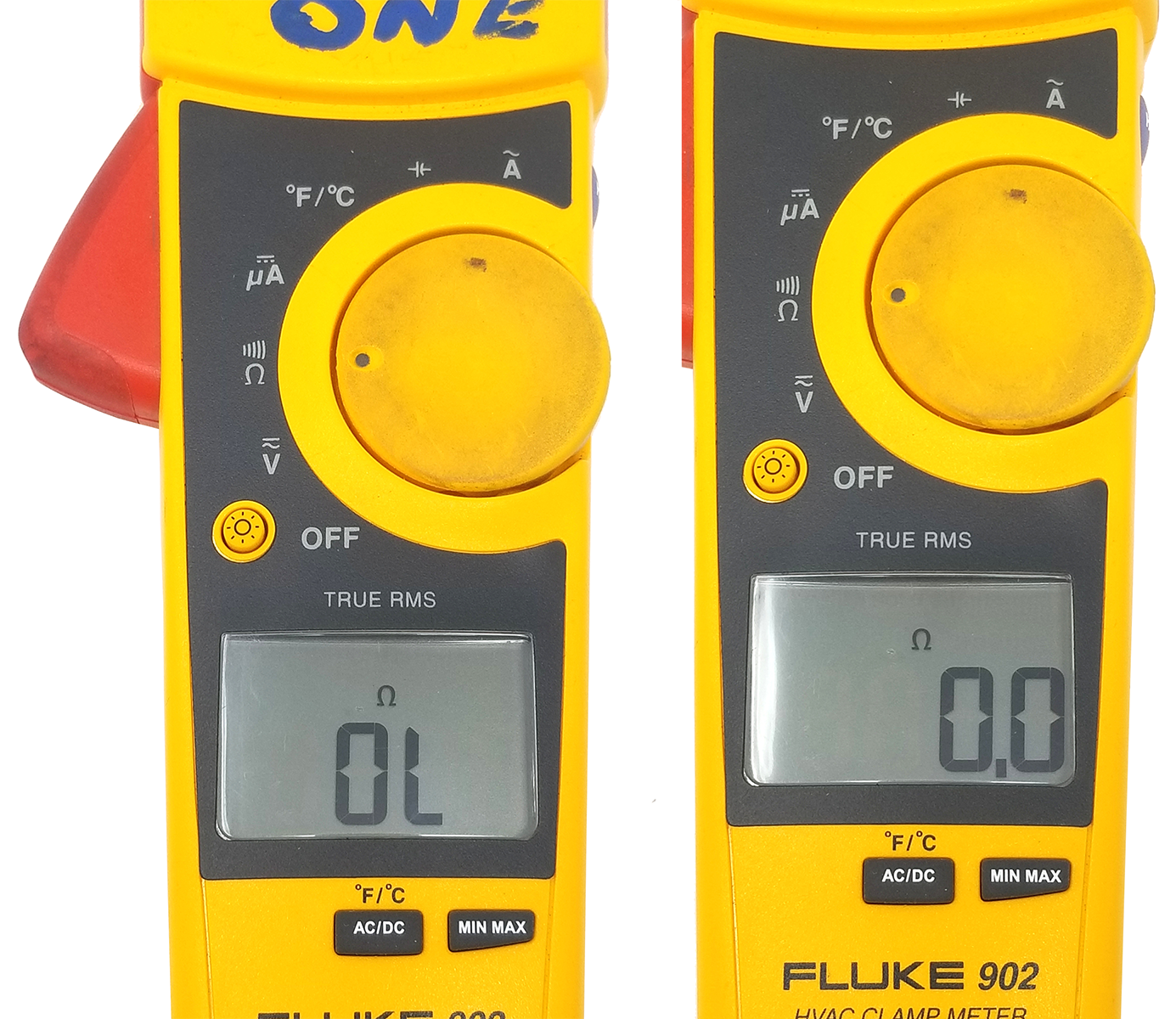
A DMM has an ohmmeter function that measures the amount of resistance in a component or circuit. The ohmmeter function is powered by a small battery that causes current flow through the tested circuit’s resistance. Therefore, a DMM set for ohms must not be used on an energized circuit. A DMM set for ohms can be used to test the continuity of a circuit or its individual components, such as a fuse or a switch. As shown in Figure 6, resistance of an open switch or faulty fuse would indicate OL (infinity) on the display, and a closed switch or good fuse would indicate a very small resistance value on the display.
Most DMMs have a similar function with an audible continuity setting. If the fuse or switch is good, the DMM will emit an audible signal, usually a steady tone whenever there is continuity. This allows the operator to test without removing their eyes from their work. The circuit must also be de-energized when using this function.
Use Digital Multimeters (DMMs)

Precautions in Handling and Using Electric Meters
The proper care of test equipment and instruments is of utmost importance, whether they are analogue or digital. The length of time an instrument retains its original usefulness and accuracy depends largely on the care it receives in the hands of the user.
The following precautions apply equally to digital and analogue meters:
- Do not drop any meter.
- Avoid tampering with precision instruments. Have them serviced by a qualified repair technician.
- Ensure that proper test leads are used when using test equipment; they must have a category rating that equals or exceeds the rating of the tester.
- Perform a resistance test of the leads to confirm that they are reliable and well-connected.
- Test a meter and leads on a known source before using the meter to test a circuit or component to ensure that the meter is working properly.
- Assume that a circuit is energized until it has been positively identified as de-energized by taking proper measurements: “Test before touch.”
- Wear appropriate personal protective equipment (PPE), as specified in CSA Z462, “Standard for Electrical Safety in Workplace.”
- Observe correct polarity on DC measurements.
- Before connecting a meter to a circuit, ensure that the function and range is set to an appropriate position. When in doubt, use a high range that you know will not be overloaded. You can always switch to a lower range, if necessary.
- Carefully check circuit connections before applying power to meters.
- Be careful not to touch any other electronic components within the equipment.
- Be careful not to touch the probe tips to each other while connected to anything else.
Voltage Measurement
AC and DC digital voltmeters must be connected in parallel with the device or circuit being measured. If the voltmeter is connected in series, its high internal impedance will act as part of the series circuit and cause a false reading on the display.
An AC voltage waveform changes polarity constantly with time, so it is not necessary to ensure correct polarity when connecting the test leads. A DC voltage should be measured with the black lead in the COM jack and connected to the negative lead of the circuit or component. The red lead should be in the V/Ω jack and connected to the positive lead of the circuit or component.
The manufacturer recommends that the black lead always be connected first when taking measurements. If a negative sign (–) is displayed in the display window, the polarity is incorrect, and the meter leads should be reversed.
Voltage Measurement with DMM
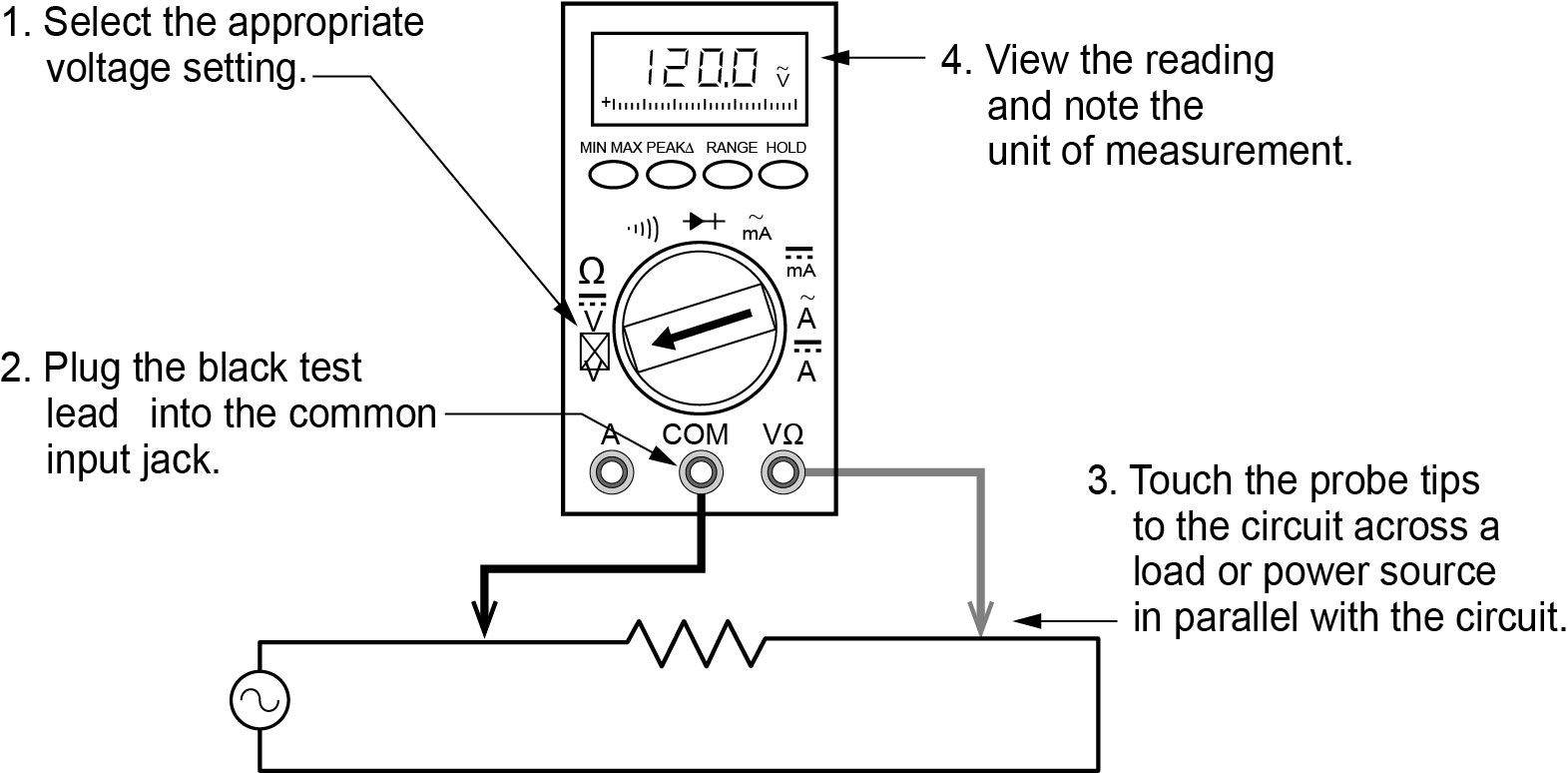
Follow these steps to measure voltage, referring to Figure 7:
- Set the function switch to DC or AC volts.
- If the voltage being measured is not known, set the range to the highest voltage. An autorange DMM will automatically select the range based on the voltage present.
- Plug the test probes into the appropriate probe jacks on the meter.
- Touch the probe tips or connect alligator clips across the source or load.
- View the reading on the display unit. Be sure to note the unit of measurement. When testing DC voltage, if a negative sign appears in the display, the polarity of the probes is incorrect and needs to be reversed.
Current Measurement
It is often necessary to measure the current flowing in a circuit to check its operation. There are two common methods of measuring current using a DMM:
- In-line ammeter method
- Clamp-on ammeter method
Most of the DMMs designed for use in the HVAC industry measure DC microamperes (µA) using only the in-line method; all AC current is measured using the clamp-on method.
Connecting a DMM In-Line to Measure Amps
As previously seen, the placement of meter leads for voltage measurements is straightforward. The leads are simply connected across or in parallel with the points of voltage to be measured.
For in-line current measurements, however, the process is slightly more complex. First, the circuit must be opened at the test points and the meter inserted in series at that opening (Figure 8). The total current must flow through the meter. To allow the measurement to be made without disturbing the circuit itself, the current meter must have very little internal resistance.
This is where a beginner must be particularly alert. If the meter is inadvertently connected across a potential difference (PD) or in parallel with a component instead of in series, the small internal resistance will permit a very large current to flow through the meter. This will most certainly damage the meter severely and perhaps the circuit as well.
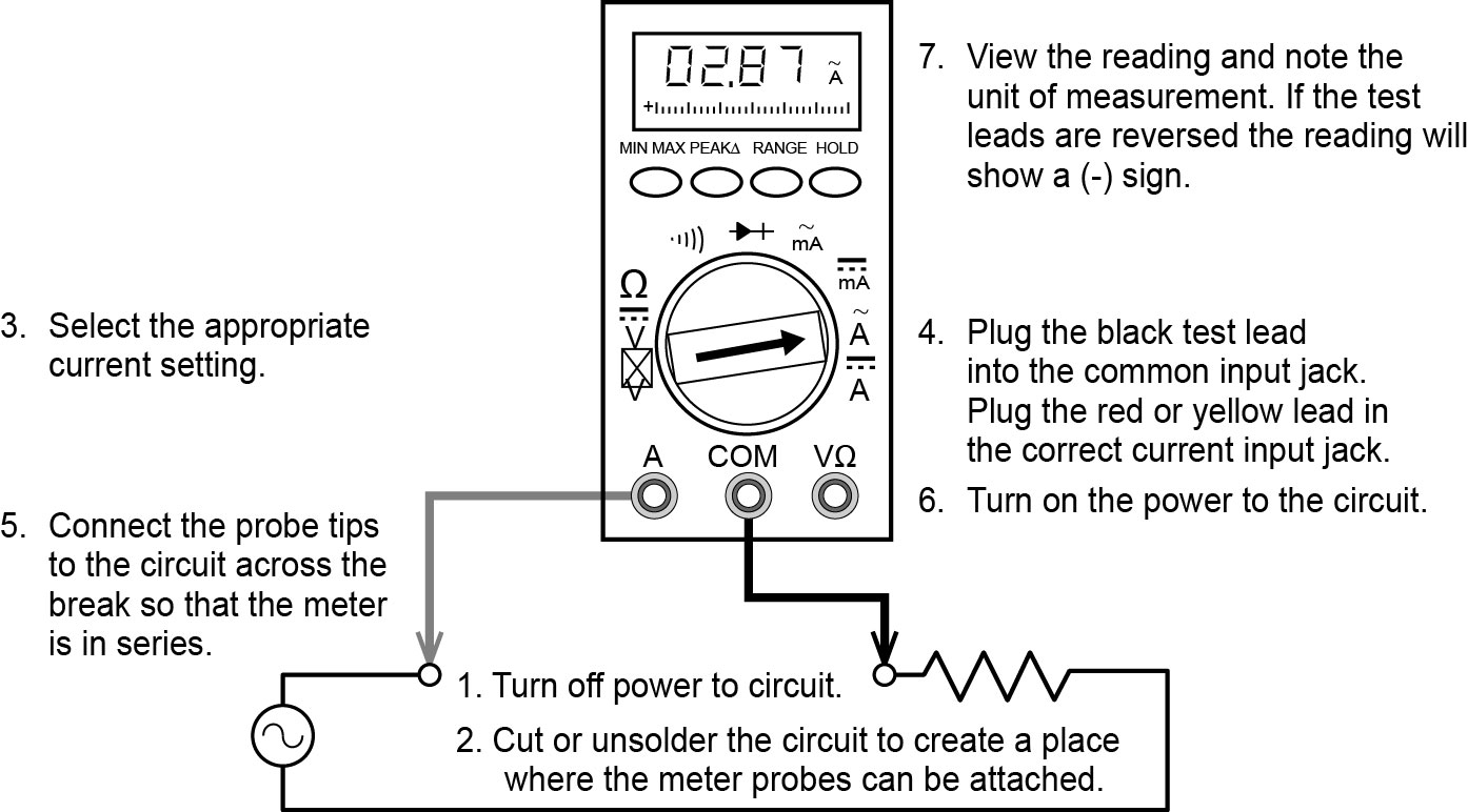
Follow these steps to measure low amperage current with test leads and refer to Figure 8:
- Turn off the power to the circuit to be measured and confirm with a voltage test.
- Open the circuit by disconnecting or unsoldering a connection at a point where you wish to measure current.
- Select the DC or AC amps function by turning the function switch to DC or AC amps.
- Plug the test probes into the appropriate probe jacks. Note that the jacks used may not be the same ones used to measure volts. Plug the red test lead into the highest current jack. If the current is higher than what the meter is rated for, use a clamp-on ammeter.
- Connect the tips of the probes across the break in the circuit, as shown in Figure 8, so that the current to be measured flows through the meter. Note that this is a series connection. Never connect the ammeter in parallel with the source or load, as this will cause a short circuit and damage the meter.
- Ensure that the ammeter is properly placed in the circuit, turn on the circuit, and read the measurement in the display window.
- Turn off the power to the circuit, and remove the in-line ammeter.
- Once the current measurements have been taken, to avoid accidentally connecting the meter in parallel, which would damage the meter, turn the function selector switch to the OFF position, then place the test leads in the common jack and the voltage jack.
Connecting a DMM Clamp Ammeter to Measure Amps
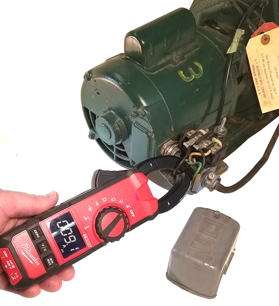
Some types of DMMs have a clamp-on or fork amperage sensing head. The spring-loaded expandable jaws, or the open fork, are positioned around a single conductor (Figure 9). This feature allows you to measure the magnetic field created by the current flowing through the wire to give an ampere reading without having to make physical contact or disconnect the circuit. This is useful when checking loads, such as those for electric motors.
It is important to realize that the current flow through two conductors in a circuit cannot be read together. In a two-wire circuit, the direction of the two electromagnetic fields is opposite to each other and cancel each other out if the meter is clamped around both wires at once.
Current measurement with a clamp-on ammeter is done as follows:
-
- Open the jaws of the ammeter by squeezing the handle.
- Close the jaws over the conductor, as shown in Figure 10. For best results, try to position the wire between the arrows, although there may not be enough room. This is where the fork type is advantageous because the prongs of the fork do not require as much room.
- Ensure that only one conductor is enclosed in the jaws. If the live and neutral conductors are both enclosed by the jaws, the meter will read zero.*
- The current reading is indicated on the ammeter display.

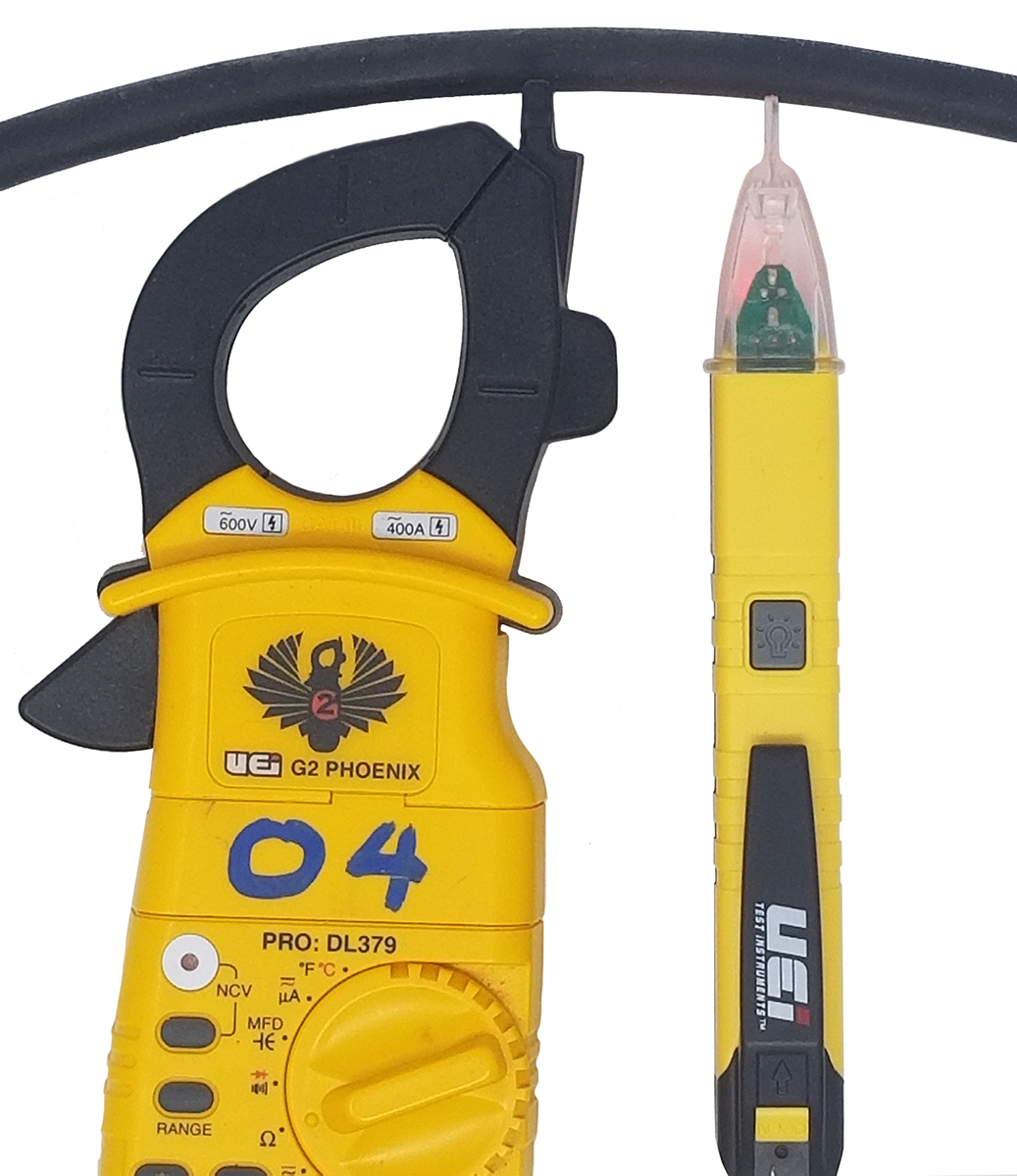
Many clamp meters have a non-contact voltage tester built into one of the tongs of the clamp. Figure 11 also shows a pocket version. Non-contact voltage testers provide an easy and safe way of ensuring that electrical conductors do not have power without having to connect to the bare wire. The tester works by detecting the electric fields associated with AC voltages. The devices indicate the presence of a voltage by lighting up, making a sound, or both.
Measuring Resistance
Even though it reads out resistance, the ohmmeter is still a current-measuring device at heart. The ohmmeter is created from a DC current meter by the addition of a group of resistors and an internal battery. The battery supplies the current flow that is eventually measured by the meter. For this reason, when using an ohmmeter, the circuit must not be live.
Since current can flow either way through a pure resistance, there is no polarity requirement for attaching the meter leads. The meter’s battery sends a current flow through the unknown resistance, the meter’s internal resistors, and the current meter.
The ohmmeter is designed so that it displays 0 Ω when the test leads are clipped together (zero external resistance). The meter reads infinite (I) resistance or over limit (OL) resistance when the leads are left open. When a resistance is placed between the leads, the readout increases according to how much current that resistance allows to flow.
Using the DMM Ohms Function to Measure Resistance
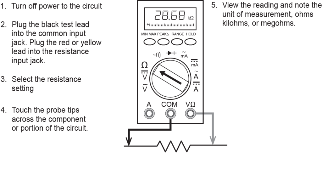
To measure resistance using the DMM ohms function, follow these steps and refer to Figure 12:
- Ensure that the power to the circuit is off. Never connect a DMM set for ohms to an energized circuit, as this will damage the meter. Always remove or isolate the component to be tested.
- Set the function switch on the DMM to resistance (Ω).
- Plug the black lead into the common jack.
- Plug the red lead into the resistance jack (Ω).
- Connect the leads together. If the battery symbol appears in the display, replace the battery. The meter should display a small amount of resistance (from about 0.2 Ω to 0.5 Ω). This is the test lead resistance. With the test leads held apart, the meter should display OL or 1, depending on the manufacturer. This indicates an infinite amount of resistance.
- Connect the test leads across the component under test and read the display. Make sure there is a good connection between the test leads and the component under test to get an accurate reading.
- After all the resistance readings have been completed, turn the DMM off to prevent the battery from draining.
Applications
The hand-held digital multimeter is one of the most valuable tools used for equipment troubleshooting in industrial, commercial, and residential applications. Some examples of where a piping tradesperson will use a DMM include:
- Gas pilot thermocouple tests
- Gas appliance millivolt control circuit tests
- 24 VAC control circuit tests on heating equipment
- Class 2 transformer tests
- Potable water heater, element, and control circuit tests
- Well pump motor and control circuit tests
- When verifying that equipment is electrically isolated for service or maintenance
 Self-Test A-4.3 Electrical Testing Instruments
Complete Self-Test A-4.3: Electrical Testing Instruments and check your answers.
If you are using a printed copy, please find Self-Test A-4.3 and Answer Key at the end of this section. If you prefer, you can scan the QR code with your digital device to go directly to the interactive Self-Test.
References
Skilled Trades BC. (2021). Book 1: Fuel gas systems, Heating and cooling systems. Plumber apprenticeship program level 2 book 1 Harmonized. Crown Publications: King’s Printer for British Columbia.
Trades Training BC. (2021). A-4: Use technical instruments and testers. In: Plumber Apprenticeship Program: Level 2. Industry Training Authority, BC.
Media Attributions
All figures are used with permission from Skilled Trades BC (2021) unless otherwise noted.
Instruments that show measured values using a scale and pointer; the pointer moves in a direct and continuous way to show how much of something is being measured. (Section A-4.3)
Instruments that use electronics to read and display exact numerical data or measurements using LEDs or LCDs as numbers on a screen, like a calculator; easier to read than analogue instruments since you don't have to interpret the numbers on a scale. (Section A-4.3)
A device automatically selects the best measurement range for what you're testing; this makes it easier because you don't have to set the range yourself—it adjusts on its own to give you the most accurate reading. (Section A-4.3)
A device used to measure electric current in a circuit. It shows the amount of current flowing through the circuit in units called amperes (amps). (Section A-4.3)
A tool used to measure how much something resists the flow of electricity (electrical resistance); it tells you the resistance in units called ohms (Ω); multimeters can serve as ohmmeters when set to resistance-measuring mode; to measure resistance, an ohmmeter applies a current to the circuit or component under test. (Section A-4.2 and Section A-4.3)
