A-4.1 Pressure Measuring Tools
Pressure measurement is the analysis of an applied force by a fluid (liquid or gas) on a surface. Pressure is measured in units of force per unit of surface area. Many instruments are used to measure fluid pressures, with different advantages and disadvantages. Pressure range, sensitivity, dynamic response, and cost all vary from one instrument design to the next.
Describe Pressure-Measuring Tools
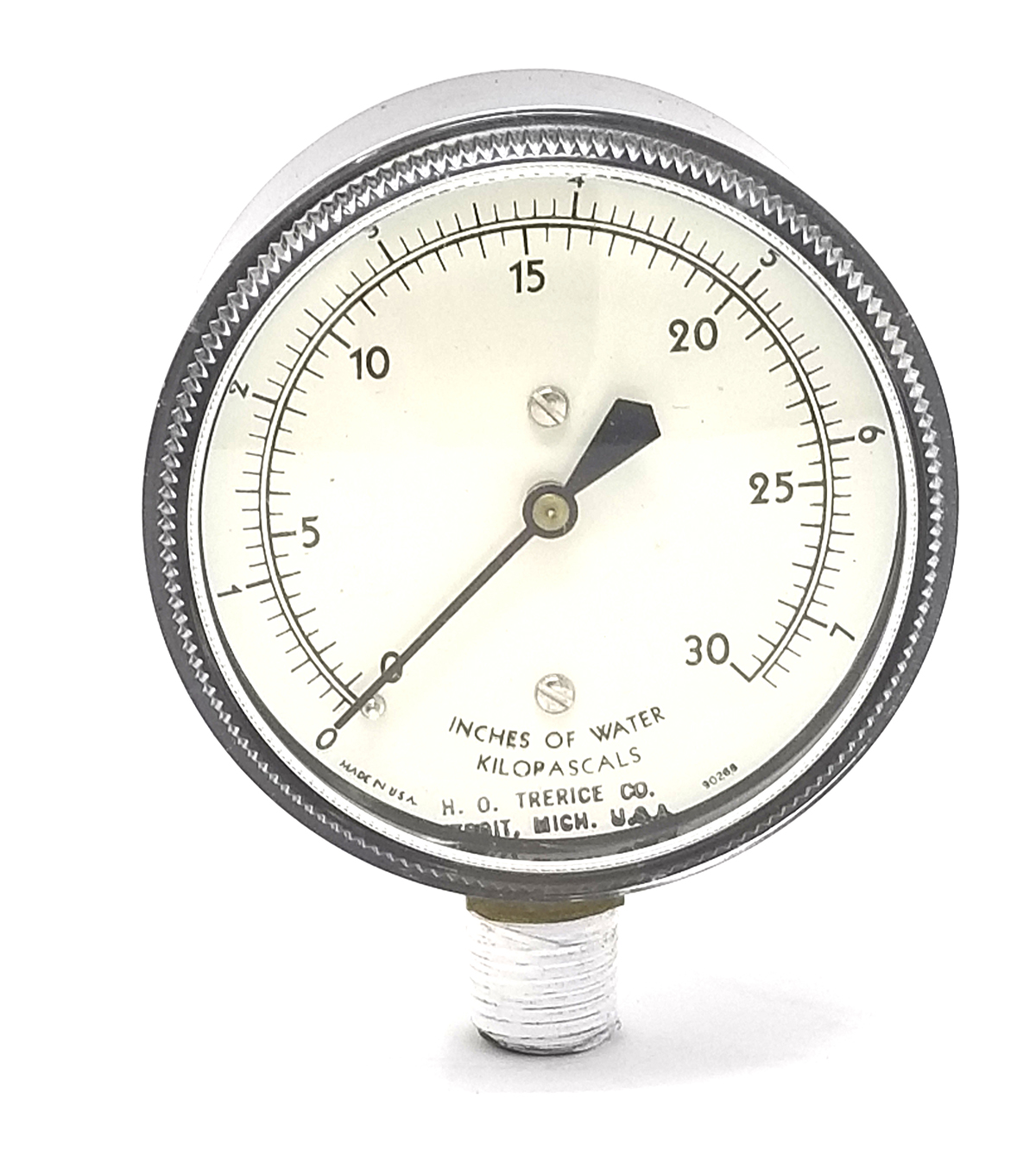
Instruments used to measure and display pressure in an integral unit are called pressure meters, pressure gauges, or vacuum gauges. The most common mechanical pressure-measuring instrument is the Bourdon tube pressure gauge (Figure 1).
Types of Pressure Measurements
A variety of units are used to express pressure, depending on the application or discipline. Some units are derived from the method originally used to measure and indicate pressure. For example, one of the earliest methods of pressure measurement, still used today, is observing the level that a column of liquid, such as water or mercury, could be supported or elevated by the pressure.
These units are still used as standard increments on many analogue gauges, while digital gauges typically offer multiple scale display options. Table 1 shows the more common pressure units and their conversion factors. The use of the unit atm (standard atmosphere) has become obsolete and been replaced by the “bar,” which is defined as exactly 100 kPa (slightly less than the current average atmospheric pressure on Earth at sea level). The inches-of-water scale, which is commonly used for low-pressure measurements, can be expressed as in H2O, in.WC, or in.Wg.
| Pressure Units | kPa | psi | in.Hg | in.WC | atm | bar |
|---|---|---|---|---|---|---|
| 1 kPa | 1 | 0.145 | 0.295 | 4.015 | 0.009869 | 0.01 |
| 1 psi | 6.895 | 1 | 2.036 | 27.68 | 0.0680 | 0.0689 |
| 1 in. Hg | 3.386 | 0.491 | 1 | 13.6 | 0.03342 | 0.03386 |
| 1 in. WC | 0.249 | 0.036 | .07355 | 1 | .002458 | 0.00249 |
| 1 atm | 101.325 | 14.73 | 29.92 | 406.793 | 1 | 1.01325 |
| 1 bar | 100 | 14.5 | 29.53 | 401.859 | 0.9869 | 1 |
Most gauges measure pressure relative to atmospheric pressure as the zero point, so this form of reading is simply referred to as “gauge pressure.” However, anything greater than total vacuum is technically a form of pressure. When the pressure is relative to a perfect vacuum, it is referred to as absolute pressure, which equals gauge pressure plus atmospheric pressure. At sea level, the pressure from the atmosphere is about 101.3 kPa; therefore, a gauge pressure of 300 kPa equals 401.3 kPa (abs).
The height above, or in some cases below, the earth’s surface, has a direct effect on atmospheric pressure. Atmospheric pressure varies with weather conditions. A barometer is a type of pressure gauge used specifically to measure atmospheric pressure. The units of measure used are inches of mercury (in.Hg). One standard atmosphere (atm) equals 29.92 in.Hg.
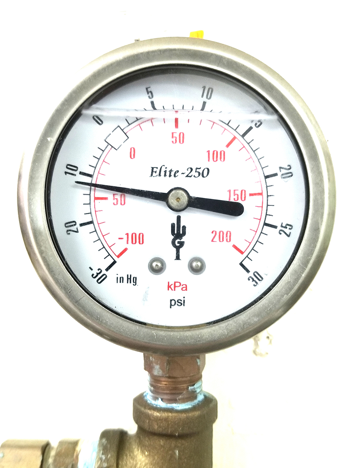
A vacuum gauge registers the amount of pressure below the atmospheric pressure. The gauge shown in Figure 2 is called a compound gauge because it can measure pressures both above and below atmospheric pressure. Notice that it is registering a vacuum reading of 12 in.Hg below atmospheric pressure, which is equivalent to an absolute pressure of about 18 in.Hg (30 −12 = 18).
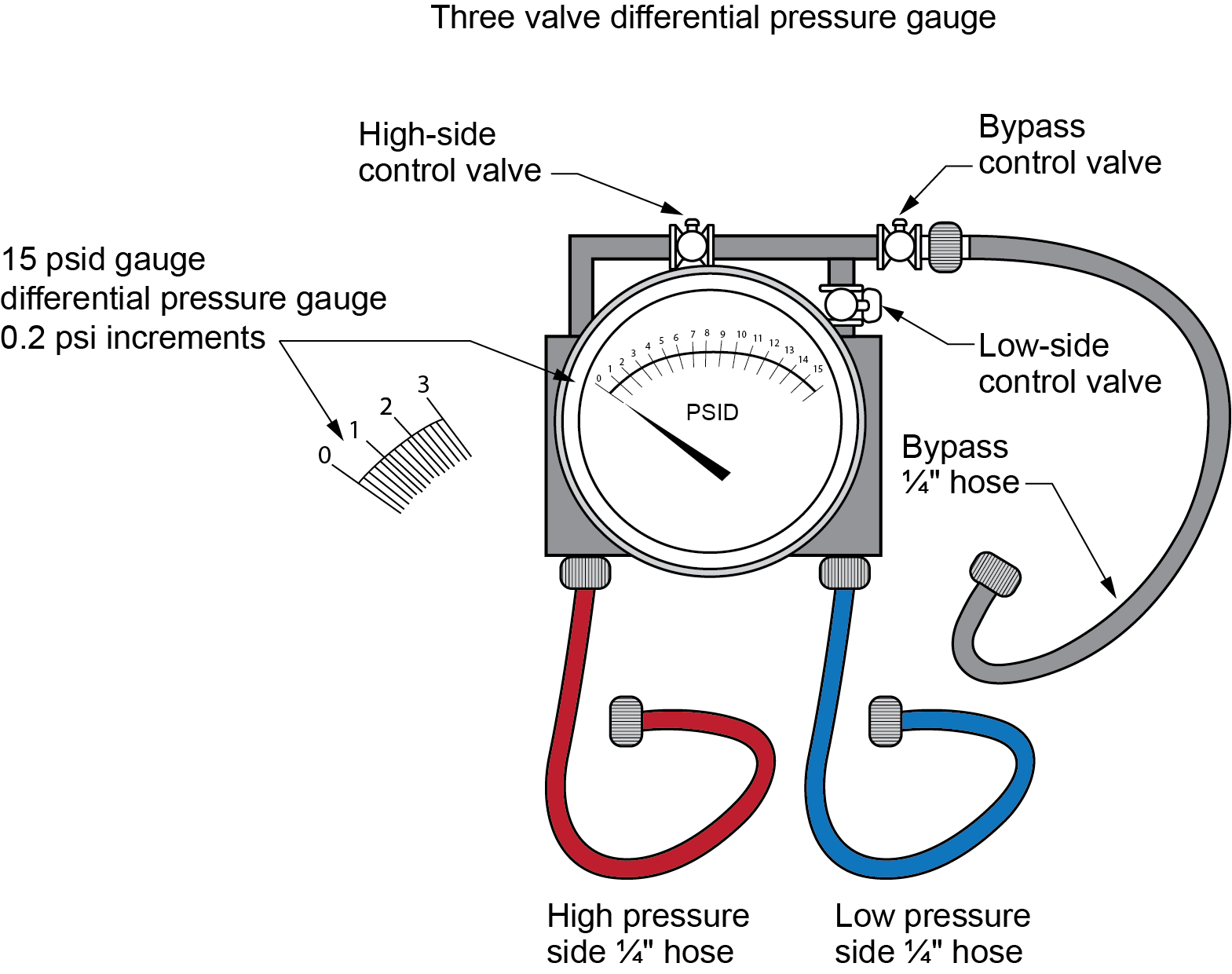
When the instrument registers the difference in pressure between two contained working fluids, it is called differential pressure. Differential pressure gauges have two inlet ports (Figure 3), each connected to one of the volumes whose pressure is being monitoring. In effect, such a gauge performs the mathematical operation of subtraction through mechanical means. Differential pressure gauges can be used to monitor air flow, check the amount of filter clogging, and test equipment operation.
Fluid Manometers
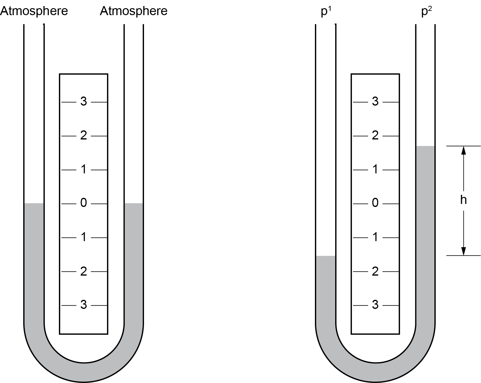
Fluid manometers consist of a liquid column in a clear tube whose ends are exposed to different pressures. The column rises or falls until the weight of the liquid column balances the pressure differential between the two ends of the tube. The simplest version is the U-tube manometer (Figure 4). With the tube half full of liquid and both legs open to the atmosphere, the level is the same on both sides, and the reading is zero. If the p1 leg were connected to check the manifold pressure of a gas appliance and the p2 leg were still open to atmosphere, the manifold gas pressure would be measured by the difference in the liquid heights in the two legs. If the fluid were water, dimension h would measure 3.0 in.
Fluids
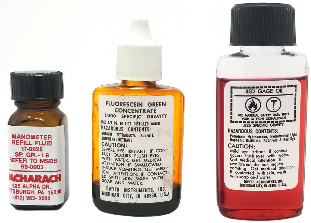
Some manometers are designed to use liquids with a different specific gravity (SG) than water, such as coloured oils (Figure 5). In these cases, the monometer’s scale may still read as inches of water column (WC), but the actual physical measurement would be adjusted. This enables the manufacturer to change the length of the instrument or design it so that the measurement is only taken on one leg.
Manufacturers will colour-code the fluid. It is important to use the correct fluid that the manometer scale is designed for. The manufacturers also make a coloured fluid that has the same SG as water for easier reading than pure water. This fluid is concentrated and needs to be mixed with water to get the larger quantity needed for a water manometer.
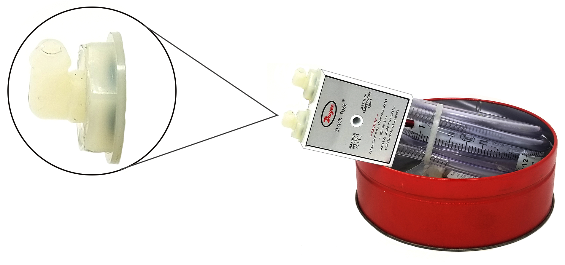
Slack Tube
The Slack Tube manometer (Figure 6) has a flexible tube that can be rolled up compactly for easy handling and storage. When unrolled, it can be attached to vertical steel surface with the built-in magnetic clips. The tube connectors are also shutoff valves that prevent the loss of fluid.
The flexible, centre-mounted scale has two inches of vertical movement for adjusting the zero location.
Inclined
An inclined manometer (Figure 7) is more accurate for lower range pressure readings, such as air flow measurements. Inclining the manometer spreads one inch of vertical lift over a much greater length, allowing the scale to be accurate to hundredths of an inch of WC.
Portable models have a swing-away foot and levelling screw setting on horizontal surfaces as well as magnets for mounting to vertical steel surfaces. They also come with shutoff pressure connections to prevent fluid loss when transporting and storing. For portable use, each time the gauge is used, the connections must be opened by turning the barbed connections one or two turns from the closed (clockwise) position, the gauge must be levelled and zeroed, and then, prior to storage, the gauge connections must be reclosed.
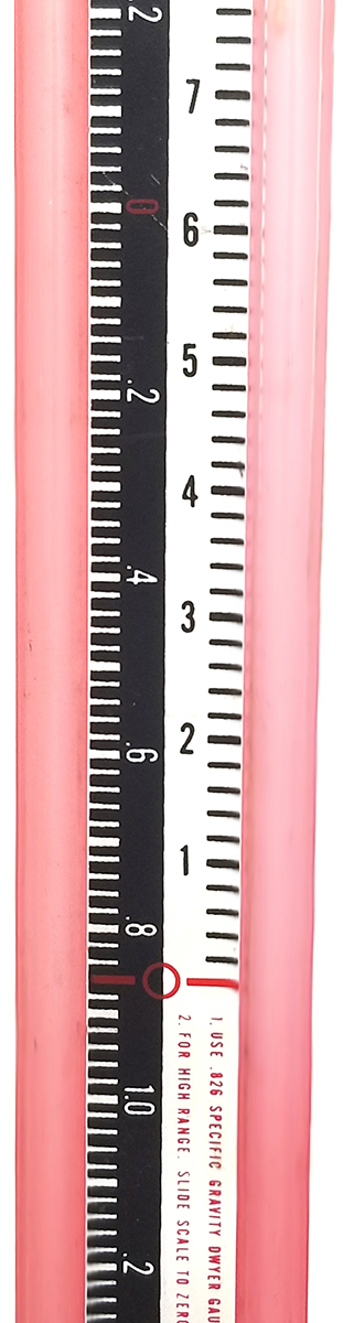
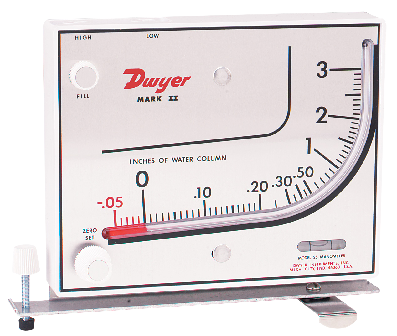
The U-tube manometer shown in Figure 8 has two scales, allowing single readings in two ranges. The higher-pressure range on the right can be used for gas pressures from 0 to 16 in.WC, or the unit can be inclined and read from the left low-range scale (0 to 2.6 in.WC) for air velocity measurement. Set the proper angle by starting with the fluid level zeroed on the right-side scale, then rotating the manometer until the fluid level is at zero on the left scale.
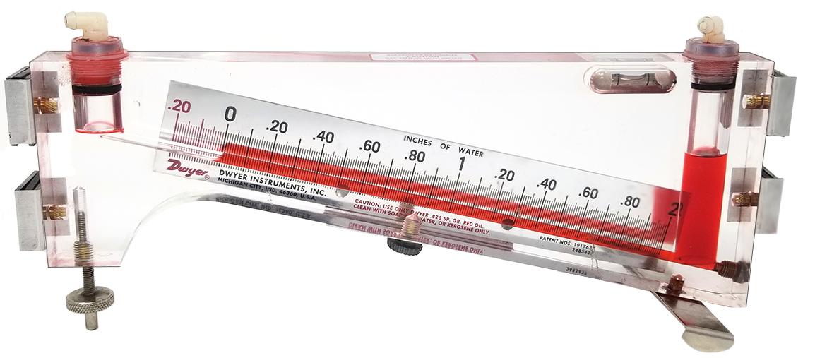
The combined inclined-vertical manometer shown in Figure 9 provides a higher range and more easily read increments at the low readings. There is also a zero-adjusting knob for fine adjustment of the liquid reservoir level.
Filling Manometers
To fill a manometer:
- Open both fittings to atmosphere.
- Slide the scale to the midpoint of travel.
- Add liquid to zero on the scale.
- Clean all fluid from the exterior of the unit.
The curvature of the fluid in a tube is called the meniscus and is caused by the adhesion between the fluid and the tube. Water and gauge oil create a U-shaped meniscus that should be read at the bottom of the curvature, whereas mercury creates an upward bulge or hump and should be read at the top.
Filling Inclined Manometers
It is important to note that when filling a manometer in preparation for a pressure reading, the water level must come to zero on both sides of the manometer. The weight of the water is critical to getting the correct pressure readings. Overfilling and underfilling will render inaccurate readings. The advantage of manometers over gauges when measuring fine pressures such as in.WC is that there is no mechanical resistance like what is encountered in a mechanical instrument, such as a Bourdon tube gauge.
To fill an inclined manometer:
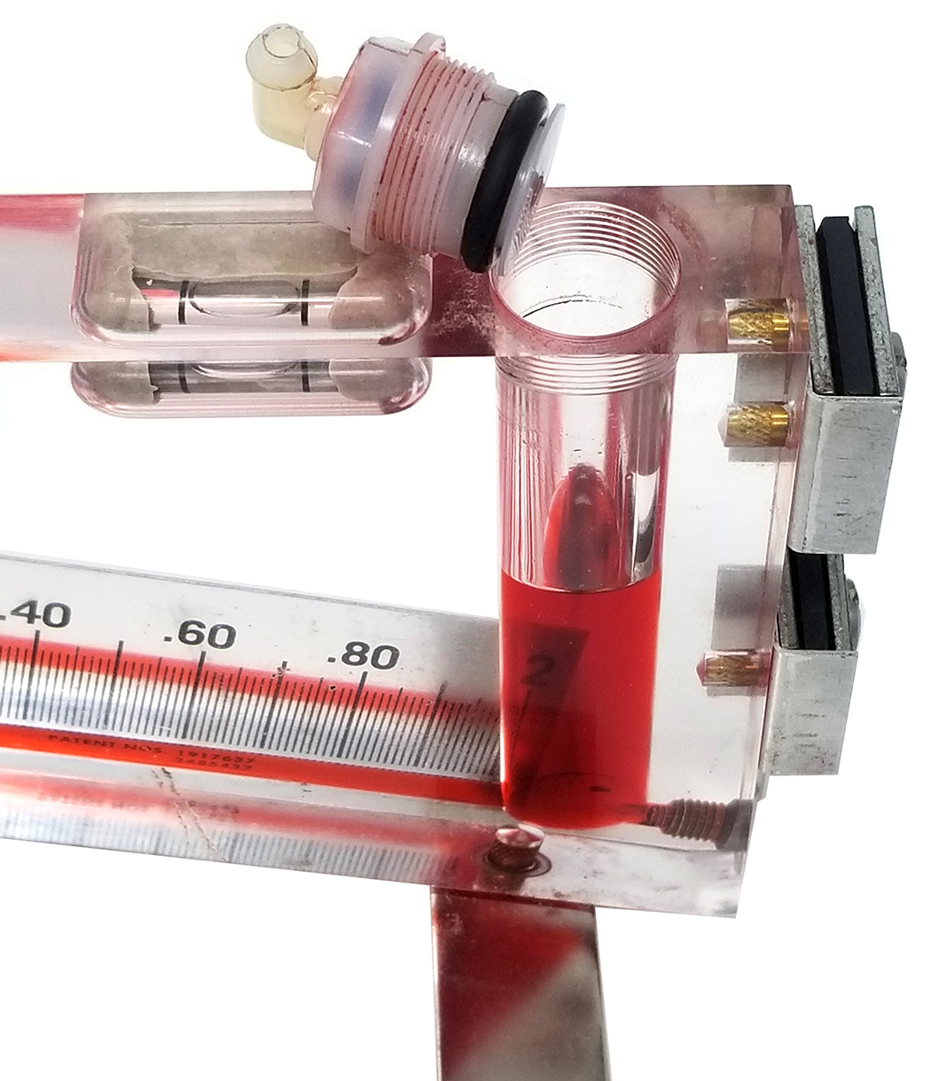
- Use a [latex]\tfrac{3}{4}[/latex] in. wrench to unscrew the entire low-pressure (right) shutoff connection fitting body (Figure 10).
- Vent the left connector by turning the elbow one or two turns counter-clockwise.
- Slowly fill the gauge with the fluid provided until the fluid rises in the indicating tube to the vicinity of zero on the scale.
- Replace the low-pressure shutoff connection fitting, opening the fitting before reinstalling it to stop fluid from being displaced out the left side.
- Close both fittings before storing.
Check the manufacturer’s specifications (specs) for the proper fluid. Different models may use fluid with different specific gravities.

When working with manometer fluids other than water, always check the manufacturer’s safety data sheet for specific hazard information, safe handling, and emergency procedures.
When filling inclined-vertical manometers with a zero-adjustment knob, turn the knob fully counter-clockwise until it stops; then, turn it clockwise approximately four full turns to centre the adjustment to allow room for adjusting either side of zero after filling (Figure 9).
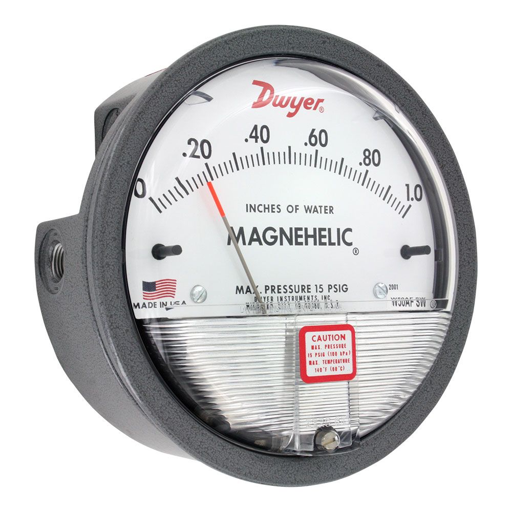
Magnehelic Gauges
A Magnehelic gauge (Figure 11) is another highly accurate pressure gauge for measuring draft conditions, determining pressure drop, or adjusting gas regulators. It uses a very sensitive diaphragm that has a pressure connection to each side. A helix turns the indicating pointer in response to the position of the magnet connected to the diaphragm. There are no mechanical linkages between the magnet and helix. The gauge must be used or mounted in the vertical position because the internal vertical diaphragm could sag and cause inaccurate readings if out of level.
Digital (electronic) manometers are the most common portable field pressure-measuring tool because they have many advantages over the previously mentioned instruments. They can measure positive, negative, and differential pressures. Digital manometers are smaller, can be used in any position, and do not require fluid. They use micro-pressure sensors that change electric resistance when pressure is applied. Figure 12 shows a digital manometer that has been opened. As can be seen, the micro-sensor has been removed from one pressure connection and is still connected to the other connection by a clear tube.
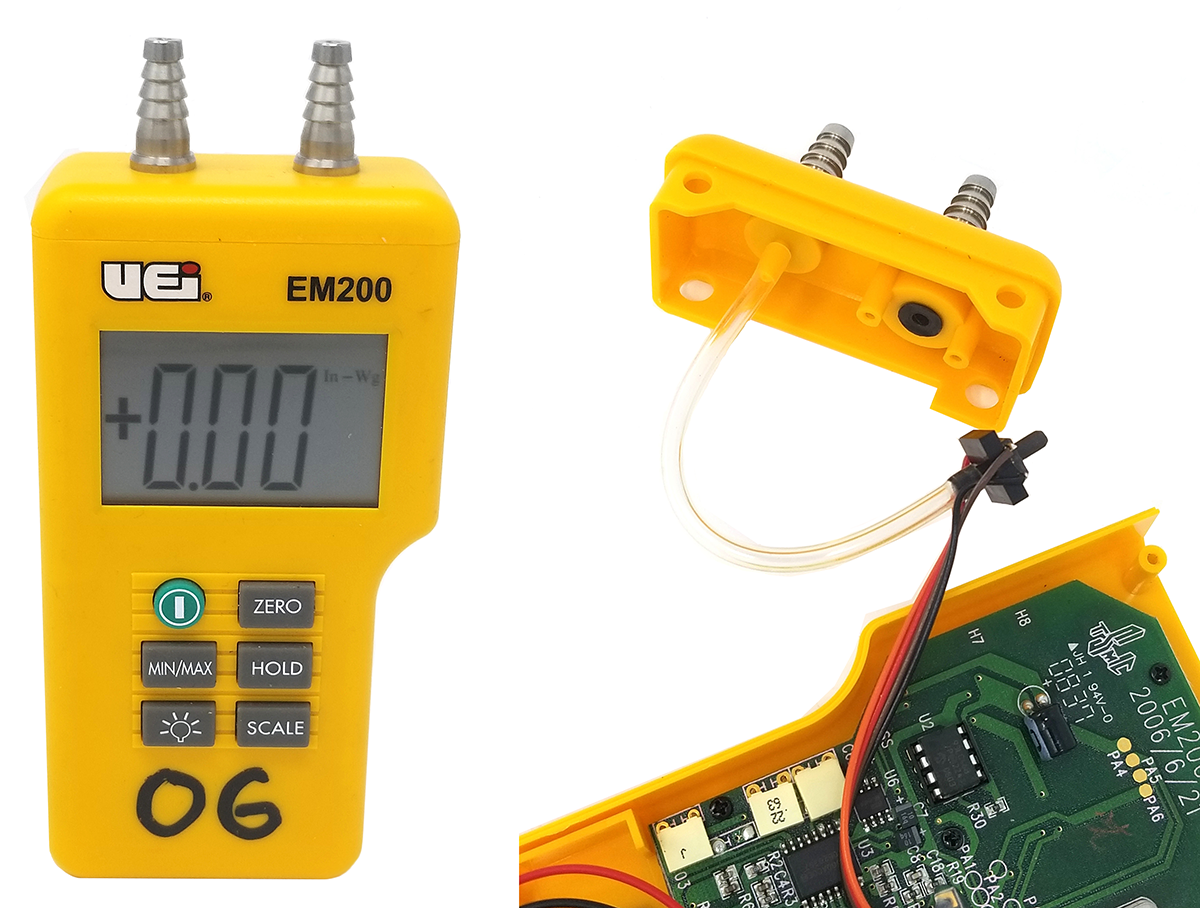
Digital manometers are available in a variety of models, depending on the range of pressures and accuracy required. A basic unit, like that shown in Figure 12, has a measurement range of 60 in. WC and is accurate to 0.03 in. WC. There is also a choice of scale displays, including psi, in. WC, mBar, or Pa. Digital manometers usually come with a protective cover, which has an internal magnet for holding onto the side of equipment.
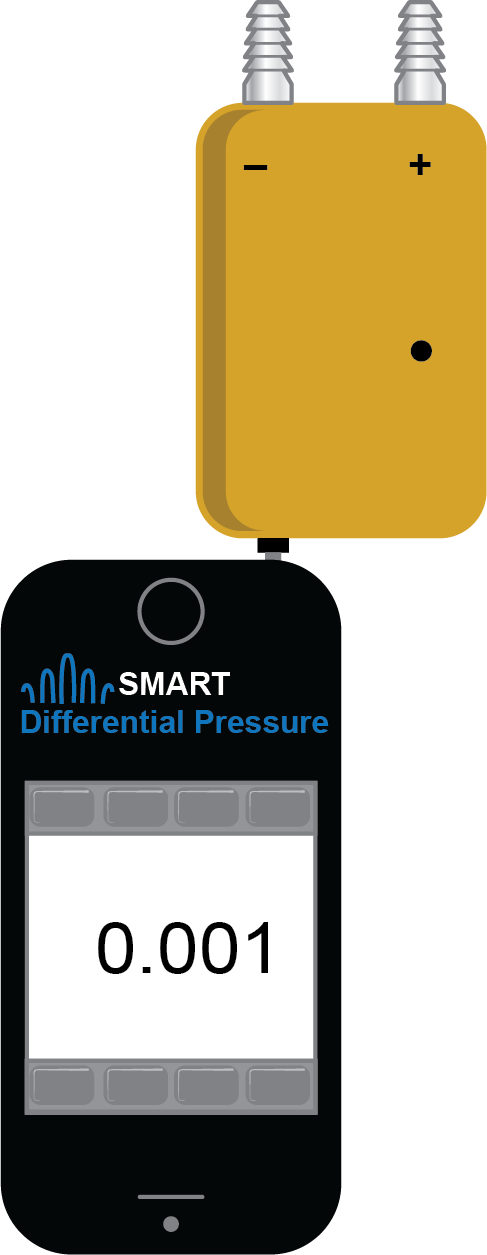
Another digital manometer option is to use a “smart” differential pressure adapter (Figure 13) designed to connect to a downloaded app on a mobile device. The app gives the mobile device all the capabilities of a typical digital manometer, with additional data logging, data sharing, and graph options.
Operation
Most electronic manometers operate similarly. Some of their typical characteristics and displays include the following:
- Negative and positive pressure sensor ports: use either port to measure a single source by venting the other port to atmosphere. Connect hose to both ports for a pressure differential reading. Some meters will also require that the pressure differential (∆P) button be activated. If the input exceeds the meter range, some form of overload (OL) symbol will be displayed; immediately disconnect from the pressure supply safely to reduce chances of damage to the unit.
- Digital display with optional backlight: using the backlight when it is not needed will significantly reduces the battery life. Some units will automatically turn off the backlight after approximately one minute.
- Power button: press to turn the device on or off. If the battery is weak, the Low Battery indicator will display. A built-in auto power-off function will turn off the meter after approximately 30 minutes of inactivity. For some units, the auto power-off function can be disabled.
- Zero button: zero the meter before using. Make sure that the meter is not pressurized, then press and hold the button. A display will indicate that the zero function has occurred.
- Hold button: press during a reading to freeze and capture the values on display. There will also be a Hold symbol on the display to flag to the user that this is not an actual measurement. Pressing the button again will return the meter to live readings.
- Scale button: repeated presses of this button will scroll through the units of measure options.
- Min/Max button: captures values for the minimum or maximum pressure measured while analyzing.
Using Portable Pressure-Measuring Instruments
Portable pressure-measuring instruments are critical diagnostic tools for proper commissioning, inspection, and maintenance of equipment. The following list includes examples of common pressure tests performed in the piping industry. Studying the specific equipment involved will provide a more thorough explanation of each procedure.
Potable Water Tests
- Initial installation pressure test: performed with test equipment that often includes a pressure gauge.
- Static system pressure test: checks the city supply pressure or verify a PRV setting. Often performed with a simple hose bib test gauge assembly.
- Operating pressure test: diagnoses system pressure loss problems. If there is a restriction in the system, it will cause a loss of pressure when the water is flowing. It may require multiple test locations to identify the problem.
- Backflow preventer operation test: ensures that the drinking water supply is protected. To perform these test procedures, use special certified differential pressure gauge assemblies.
- Air pre-charge test: checks air pre-charge on well pump pressure tanks or expansion tanks when on a municipal water supply. A simple tire gauge can be used to verify or check the pre-charge of an expansion tank when the system pressure is bled.
- Filter pressure drop tests: checks the amount of restriction caused by a filter, which would indicate whether the filter requires cleaning or replacement. Typically, pressure gauges should be permanently installed on the supply and return of the filter piping. If not, they would need to be connected.
Hydronic Heating System Tests
- Initial installation pressure test: performed with test equipment that often includes a pressure gauge.
- System pressure test: verifies the proper setting of the PRV. Typically, there would be a permanent pressure gauge on the outlet that could be used.
- Setting flow rates on circuit balancing valves: a water pressure differential gauge measures the pressure loss across balancing valves to calibrate the proper flow rate.
Gas System Tests
- Initial installation pressure test: performed with test equipment that often includes a pressure gauge.
- Gas delivery pressure check: verifies that the utility meter set or propane service regulator matches the system design. Pressure-measuring equipment needs sufficient pressure range; residential systems are maximum 2 psi, but a commercial system could be higher. The utility meter set may have pressure test plugs for connecting, or a propane service regulator may have pressure inlet and outlet test plugs built into the regulator body.
- System regulator operating pressure settings test: verifies that the regulator is able to maintain the required flow rate. If the regulator flow capacity is inadequate, the outlet pressure will drop. The regulator may have an outlet test plug, or the appliance gas valve may have an inlet test plug or port.
- Piping operating pressure loss test.
- Appliance regulator pressure settings check: (also referred to as a manifold pressure test) verifies that the gas valve regulator has been set up correctly. If an appliance is underfired, this is one of the first checks that should be made. The manometer can be connected to the outlet pressure port of the appliance gas valve, or there may be a test plug in the manifold piping.
- System static pressure leak test: troubleshoots components, such as automatic gas valves, that would not have been connected during the installation pressure test. If a manometer is connected to a charged gas supply system, all gas equipment is shut down and the manometer is observed for any change. If the pressure drops and all connections have been checked, an appliance gas valve may be faulty.
- Regulator lockup (tightness of closure) pressure test: keeps the inlet pressure to an appliance below 14 in.WC; otherwise, the internal gas valve will be damaged. For example, a propane service regulator may be set to an operating pressure of 10 in.WC. When all appliances are shut off, the pressure will increase slightly before the regulator achieves positive lockup. A manometer connected to the inlet pressure port of one of the appliances can confirm that the pressure does not continue to increase.
- Appliance pressure switches test: senses proper combustion blower operation. If they are malfunctioning, it may be the electro-mechanical contacts. Test them first in place to confirm that they are getting adequate pressure by connecting a manometer into the sensing line.
Air Duct Pressure Tests
- Low pressure tests: performed to high accuracy with an inclined manometer, Magnehelic gauge, or digital manometer.
- Duct static pressure tests: checks the amount of resistance to air flow within an operating duct system. This information is used to check the fan capacity and speed settings. Multiple static pressure readings can be used to analyze the pressure drop across sections of ducting, fittings, filters and coils, or total pressure drop across the fan.
- Velocity pressure tests: measures the air pressure in a duct that parallels the direction of air flow. Special probes are required that are inserted into the air stream and connected to the pressure instrument. The velocity pressure reading is then used to calculate the air speed and volume of air flow in the duct.
Pressure Connection Ports and Adapters
Use the pressure-measuring instruments requires flexible clear vinyl or silicone rubber tubing and an assortment of adapters to match the different types of equipment connection ports. The pressure-measuring instrument and some equipment ports have tapered, barbed connections designed to fit a range of tube sizes, from 5 mm to 8 mm ID.
Assess the connection port on the equipment and select the appropriate adapter. The following are some examples of adapters and connection ports.

Figure 14 shows 5 mm and 8 mm barbed adapters for connecting to [latex]\tfrac{1}{8}[/latex] in. NPT. This is a common type of connection on the test ports of gas valves. A [latex]\tfrac{3}{16}[/latex] in. hex key is often required to remove the [latex]\tfrac{1}{8}[/latex] in. NPT plug.
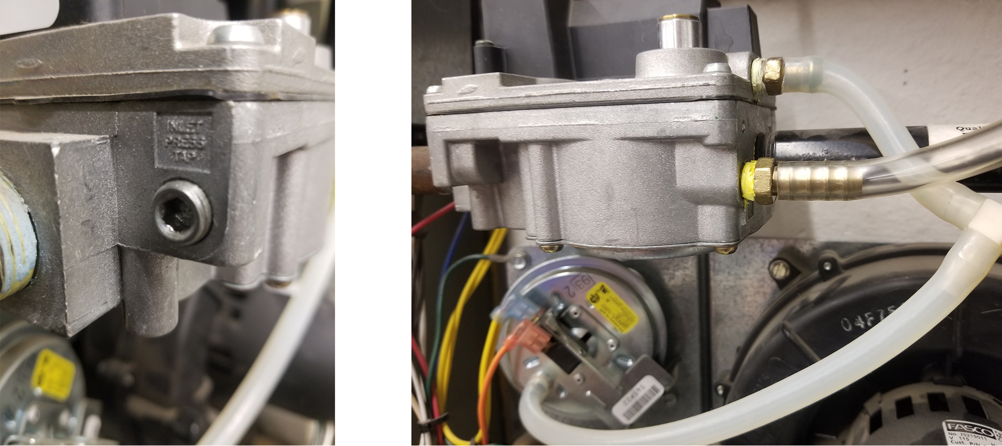
The gas valve shown in Figure 15 has [latex]\tfrac{1}{8}[/latex] in. NPT plugs on each end for testing the inlet and outlet pressure. The picture on the right shows the manometer tubing connected to the outlet pressure port to check the manifold pressure.
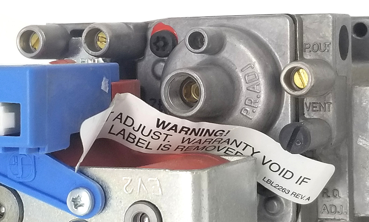
Many modern gas valves no longer have [latex]\tfrac{1}{8}[/latex] in. pipe taps for test ports. Instead, they have a tapered boss with a small screw valve inside. The valve shown in Figure 16 has, from left to right, inlet, intermediate, and outlet pressure test ports.
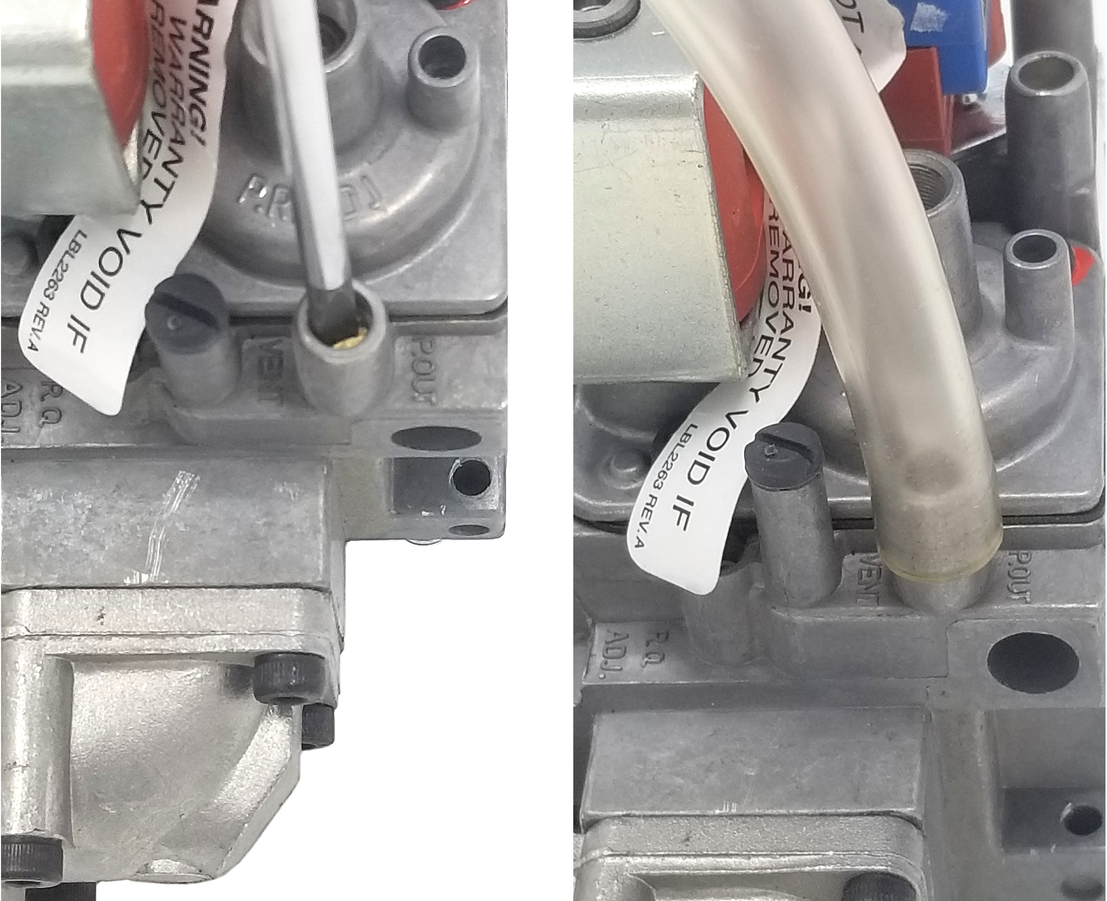
To connect the test equipment, with the gas shut off, simply open the internal screw valve about one turn and slip a hose directly over the boss (Figure 17). No adaptor is needed. Then, turn on the gas supply and measure the pressure.
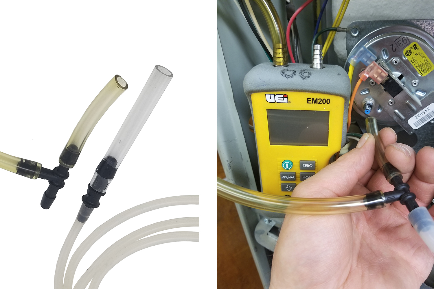
For some connections, the tube may require a barbed reducer or a tee (Figure 18). The reducer shown on the left increases the 3 mm silicone rubber to the 8 mm vinyl tube. The image on the right shows an 8 mm barbed tee being inserted into a sensing line to check the pressure switch operation for a furnace inducer fan.
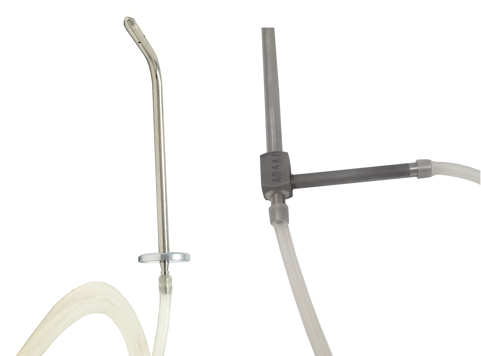
For duct air flow measurements, special tips are inserted into the ducting through 9 mm drilled holes. The tips are then connected to the pressure-measuring instrument with silicone rubber tubing (Figure 19). The image on the left shows a static pressure tip with a barbed connection. The silicone rubber tubing is very flexible and can be expanded to fit over the device, as shown by the pitot tube in Figure 19 on the right.
Another useful method of checking system pressure is by way of special pressure and temperature test port plugs (P/T plug and Pete’s Plug ®). The [latex]\tfrac{1}{4}[/latex] in. MIP (male iron pipe) plug shown third from the left in Figure 20 is permanently mounted in a pipe line at recommended test points. The plug has an internal self-sealing pierceable diaphragm made of neoprene or Nordel, depending on the fluid pressure or temperature of the application. The cap protects the valve and provides an additional seal.
After the cap has been removed, the pressure probe adapter shown on the left is inserted through the self-sealing diaphragm, shown on the right. The probe comes with an aluminum sleeve to protect the [latex]\tfrac{1}{8}[/latex] in. probe when not in use. Notice the inserted probe has a [latex]\tfrac{1}{4}[/latex] in. MIP by [latex]\tfrac{1}{4}[/latex] in. flare adapter installed onto it for use with the water hose connections of a differential pressure gauge.

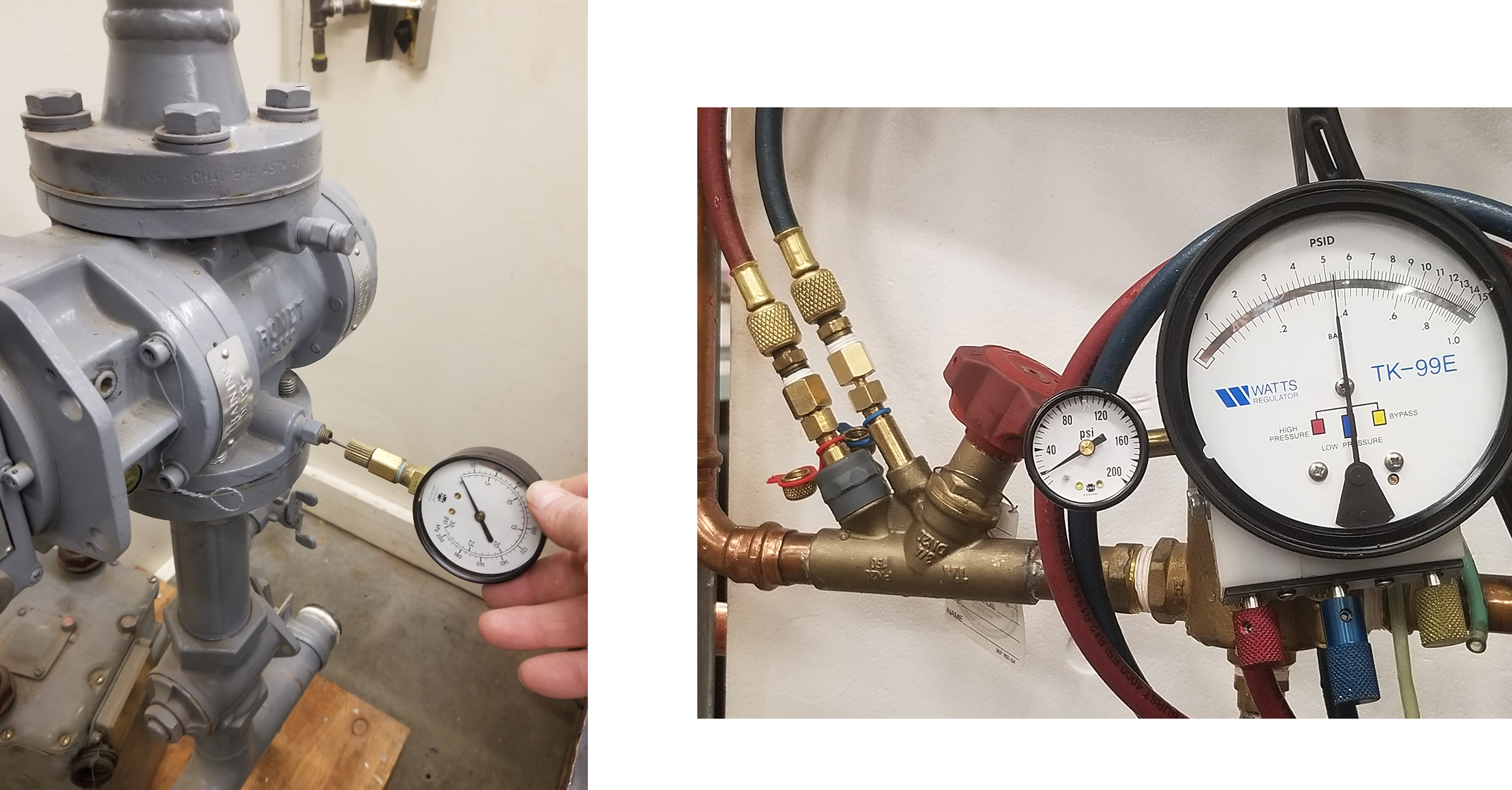
Test port plugs can also be used for temperature tests with the proper [latex]\tfrac{1}{8}[/latex] in. insertion probe. P/T plugs are commonly used in the natural gas and hydronic industries. Figure 21 shows two examples of pressure tests being taken using the P/T plugs. The meter’s gas pressure is being checked on the left. The image on the right shows two test probes measuring the pressure differential while setting the flow on a hydronic balancing valve.
 Self-Test A-4.1 Temperature Measuring Instruments
Complete Self-Test A-4.1: Pressure Measuring Tools and check your answers.
If you are using a printed copy, please find Self-Test A-4.1 and Answer Key at the end of this section. If you prefer, you can scan the QR code with your digital device to go directly to the interactive Self-Test.

References
Differential Pressure Adapter w/ App Compatibility DPA1 [adapted image]. (n.d.). UEI Test Instruments. https://www.ueitest.com/ECommerce/product/dpa1/dpa1
Mawle, R. V. (2015). Cross connection control for plumbing and piping trades: Plumber apprenticeship program Level 3. BCcampus. https://collection.bccampus.ca/textbooks/cross-connection-control-for-plumbing-and-piping-trades-plumber-apprenticeship-program-level-3-bccampus-93/
Series Mark II molded plastic manometers. (n.d.). Dwyer. https://dwyer-inst.com/series-mark-ii-molded-plastic-manometers.html
Skilled Trades BC. (2021). Book 1: Fuel gas systems, Heating and cooling systems. Plumber apprenticeship program level 2 book 1 Harmonized. Crown Publications: King’s Printer for British Columbia.
Trades Training BC. (2021). A-4: Use technical instruments and testers. In: Plumber Apprenticeship Program: Level 2. Industry Training Authority, BC.
Media Attributions
All figures are used with permission from Skilled Trades BC (2021) unless otherwise noted.
- Figures 2, 5-8, 10, 12 and 14-21 are by Rod Lidstone and are used under a CC BY licence.
- Figure 3 Differential pressure gauge used for testing backflow prevention assemblies is adapted from Richard Mawle/BCcampus (2015) and is used under a CC BY NC 4.0 licence.
- Figures 9 and 11 SERIES MARK II MOLDED PLASTIC MANOMETERS and SERIES 2000 MAGNEHELIC® DIFFERENTIAL PRESSURE GAGES are from Dwyer (n.d.) and used with permission.
- Figure 13 Differential pressure adaptable for the smartphone was adapted from UEI Test Instruments (n.d.) and is used for educational purposes under the Fair Dealing guidelines.
The analysis of an applied force by a fluid (liquid or gas) on a surface; pressure is measured in units of force per unit of surface area. (Section A-4.1)
The pressure measurement by most gauges, this is the pressure measurement relative to atmospheric pressure as the zero point. (Section A-4.1)
When the pressure is relative to a perfect vacuum, it is referred to as "absolute pressure," which equals gauge pressure plus atmospheric pressure. (Section A-4.1)
A type of pressure gauge used specifically to measure atmospheric pressure. The units of measure used are inches of mercury (in. Hg). (Section A-4.1)
A type of gauge that will register the amount of pressure below the atmospheric pressure. (Section A-4.1)
A type of gauge that can measure pressures both above and below atmospheric pressure. (Section A-4.1)
The difference in pressure between two contained working fluids. (Section A-4.1)
A type of gauge with two inlet ports, each connected to one of the volumes whose pressure is to be monitored; this gauge can be used to monitor air flow, check the amount of filter clogging, and test equipment operation; it performs the mathematical operation of subtraction through mechanical means. (Section A-4.1)
An instrument designed to measure the pressure of fluids, usually gases or liquids; it features a U-shaped tube filled with a liquid like mercury, water, or light oils; the column will rise or fall until the weight of the liquid column balances the pressure differential between the two ends of the tube. The simplest version is the U-tube manometer. (Section A-4.1)
A method for measuring pressure, defined as the pressure produced by a 1-inch by 1-inch column of water of a specified height; useful for expressing low pressures, such as describing 0.072 psi as 2 inches of water. (Section A-4.1)
Devices used for measuring velocity and static pressures, conducting leakage, fan, and blower tests, calibrating control devices, checking gas pressure, and various other applications; consist of a flexible tube that can be rolled up compactly for easy handling and storage, and when unrolled, it can be attached to vertical steel surface with the built-in magnetic clips; the tube connectors are also shutoff valves that prevent the loss of fluid. (Section A-4.1)
A device used to measure lower range pressure readings, such as air flow measurements. By inclining the manometer, you can spread one inch of vertical lift over a much greater length, allowing the scale to be accurate to hundredths of an inch of WC [water column]. (Section A-4.1)
A type of gauge that measures the pressure of liquids and gases; it uses an elastic tube that bends under pressure, moving a pointer to indicate the pressure on a scale. This device can measure pressures up to 100,000 psi (70,000 newtons per square cm). (Section A-4.1)
A highly accurate pressure gauge for measuring draft conditions, determining pressure drop, or adjusting gas regulators. It uses a very sensitive diaphragm that has a pressure connection to each side. (Section A-4.1)
The most common portable field pressure-measuring tool due to its many advantages over traditional instruments; it uses micro-pressure sensors that alter electrical resistance when pressure is applied and can measure positive, negative, or differential pressures; this tool is compact, can be used in any position, and does not require fluid. (Section A-4.1)
